Low Pass vs High Pass Filter | Explanation and Comparison
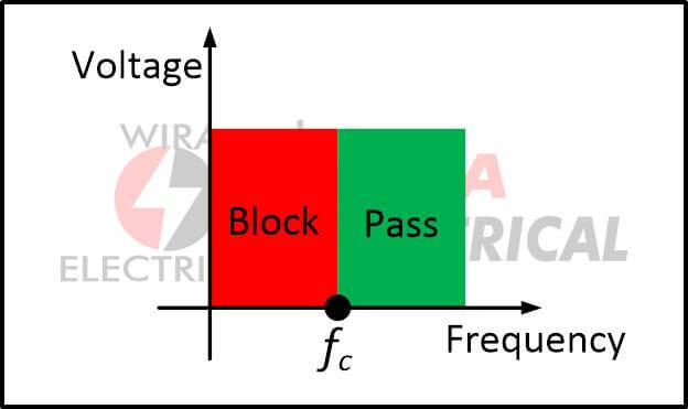
The frequency range that low pass vs high pass filter pass is the most significant distinction between them.
When we talk about a high pass filter, we’re talking about a circuit that allows high frequencies to flow through while blocking low frequencies.
Low pass filter, on the other hand, is an electrical circuit that allows low-frequency signals to flow through while blocking high-frequency signals.
You could be wondering which frequency range is high and which is low. Cut-off frequency is a word used to describe filters that presume a threshold value.
What is a Filter
Filters are electronic circuits that eliminate a portion of an AC signal. A capacitor filter is one type of filters.
A low pass filter allows signals lower than a cut-off frequency to pass, whereas a high pass filter allows signals higher than a cut-off frequency to pass.
The frequency of the cutoff is governed by the circuit’s components.
It’s critical to understand that filters don’t generate signals or modify the frequency of an object. A high-pass filter, for example, cannot produce the high frequencies that it outputs.
Instead, the input waveform has a mix of high and low frequencies, with the low frequencies being blocked by the high-pass filter.
Active filters have amplifiers that increase the filter’s output, giving the impression that the filter is creating a signal that didn’t exist in the input waveform.
However, in the filter circuit, unwanted frequencies are filtered away, while desired frequencies are amplified.
Attenuation is the process of removing undesirable frequencies. High frequencies are primarily attenuated by a low pass filter, while low frequencies are mostly attenuated by a high pass filter.
A combination of a resistor and a capacitor is used in both low pass and high pass filters. Both resistors and capacitors contribute to the circuit’s overall impedance in an AC circuit.
Resistors, much like in DC circuits, contribute resistance. The capacitive reactance of capacitors is dependent on the frequency of the incoming AC signal. The sum of the resistance and reactance is the total impedance.
Low Pass vs High Pass Filter Definition
Signals with frequencies above this cut-off frequency have low reactance, whereas signals with frequencies below this cut-off frequency have high reactance.
The low pass filter has a low reactance to signals with frequencies below the cut-off frequency, allowing low frequencies to pass, but a high reactance to high-frequency signals, preventing them from passing.
Let’s start with the filter’s components before moving on to the filter’s operational mechanism. Electronic components such as a resistor, capacitor, amplifier, and others are required for creating a filter, whether it is a high pass filter (HPF) or a low pass filter (LPF).
The important thing to remember here is that if you use passive components like a resistor or a capacitor, the resulting filter is referred to as a passive filter. If you want to use the amplifier in your filter circuit to boost the gain of the filtered signal, you’re constructing an active filter.
So far, we’ve looked at the key differences between high-pass and low-pass filters, as well as the components that determine whether they’re active or passive. Let’s look at some more noteworthy distinctions using a comparison chart.
What is Cutoff Frequency
Both low pass and high pass filters use a resistor and a capacitor combination. In an AC circuit, both resistors and capacitors contribute to the overall impedance.
Resistance is provided by resistors, just as it is in DC circuits. The frequency of the incoming AC signal affects the capacitive reactance of capacitors. Total impedance is the sum of resistance and reactance.
Because capacitive reactance is proportional to the frequency of the signal, filters can be built to raise reactance considerably above or below the cut-off frequency.
The reactance of a low-pass filter will increase above the cut-off frequency, with little or no reactance below the cut-off frequency.
A high pass filter will be designed to boost reactance below the cut-off frequency while having little or no reactance above it.
What is Low Pass Filter
In a low pass filter, the capacitor and resistor positions are switched around to get the desired output. When the input signal is applied to a low pass filter circuit, the resistance acts as a constant blockage, but the output signal is affected by the position of the capacitor.
If a high-frequency signal is placed into a low-pass circuit, it will pass through resistance, which will provide the usual resistance, but the capacitor will provide zero resistance. This is because the capacitor’s resistance to high-frequency signals is zero, but its resistance to low-frequency signals is unlimited.
Any frequency component over the cut-off frequency would be blocked by an ideal low pass filter, however low pass filters aren’t perfect.
Both high and low pass filters employ a resistor and capacitor combination, although the order is inverted in each. The input signal is supplied directly to the resistor in a low pass filter, and the output is monitored across the capacitor:

The circuit design clearly shows that if a high-frequency signal hits the low pass filter circuit, the capacitor will allow it to pass and the signal will be sent to ground. The output voltage obtained in this case is zero since the full voltage is transmitted to ground.
However, if a low-frequency signal enters a low-pass filter circuit, the output will be generated because the resistance will supply the same obstruction as a high-frequency signal, but the capacitor will provide infinite resistance.
As a result, the signal cannot pass through the capacitor circuit in this situation. As a result, the output terminal receives the complete low-frequency signal.
The low pass filter’s properties are determined by the interaction of capacitive reactance and resistance, both of which contribute to the overall impedance.
The resistor’s contribution to impedance (i.e. resistance) is unaffected by frequency, but capacitive reactance is inversely proportional to frequency.
The capacitive reactance is high at low frequencies and low at high frequencies, and this value can be expressed with the equation below,
XC = reactance of the circuit
f = cutoff frequency
C = capacitance of the capacitor
The capacitive reactance and its effect on the voltage drop across the capacitor, which is the output voltage, is a simple way to think about low pass filters.
The capacitive reactance is low at high frequencies. The capacitor permits the signal to travel to ground without causing a large voltage drop across it.
The capacitive reactance is high at low frequencies, though, and the capacitor has a significant voltage drop across it. A higher voltage drop indicates a higher circuit output voltage.
What is High Pass Filter
A high pass filter attenuates low frequencies preferentially, allowing high frequencies to pass while low frequencies are blocked.
Only high-frequency signals pass through a high pass filter, which attenuates low-frequency signals. Although it attenuates high-frequency signals as well, the attenuation factor is so minimal that it can be overlooked.
You’re probably wondering what goes into the design of a High Flow filter, what makes it enable high-frequency signals to pass through while blocking low-frequency sounds. The characteristics of the capacitor and resistor can be used to achieve this.
The input signals are applied to the capacitor, and the output voltage is acquired by measuring the voltage across the resistor. The resistance of the resistor and the resistance of the capacitor are referred to as reactance.
Any frequency component below the cut-off frequency would be blocked by an ideal high pass filter, however high pass filters aren’t perfect.
Both high and low pass filters employ a resistor and capacitor combination, although the order is inverted in each. The input signal is supplied directly to the capacitor in a high pass filter, and the output is monitored across the resistor:

The role of capacitive reactance and resistance, which both contribute to total impedance, determines the characteristics of the high pass filter.
The resistor’s contribution to impedance (i.e. resistance) is unaffected by frequency, but capacitive reactance is inversely proportional to frequency.
The capacitive reactance is high at low frequencies and low at high frequencies, and this value can be expressed with the equation below,
The reactance is inversely proportional to the cutoff frequency, as shown in the preceding equation. When the frequency of the input signal is high, the reactance will be reduced. However, if the signal’s frequency is low, the reactance will be large.
The capacitive reactance and its effect on the voltage drop across the resistor are an easy way to think about high pass filters.
The capacitive reactance is large at low frequencies, and the capacitor has a significant voltage drop across it. As a result, the majority of the voltage drop happens across the capacitor, leaving only a little voltage loss across the resistor.
The capacitive reactance is low at high frequencies. As a result, the resistor has the majority of voltage drop, resulting in a large output voltage at high frequencies.
I hope you now understand why a high pass filter allows high frequencies to flow through while preventing low frequencies from passing through.
Low Pass vs High Pass Filter Table Comparison
Below is the table comparison for low pass vs high pass filter.

Low Pass vs High Pass Filter : What’s the Difference?
- The main difference between a high pass and a low pass filter is that the former passes signals with frequencies higher than the cutoff frequency, whereas the latter passes signals with frequencies lower than the cutoff frequency.
- The circuit design of the high pass and low pass filters differs as well; the high pass filter has a capacitor followed by resistance in parallel. The low pass filter circuit is made up of a resistor and a capacitor.
- The low pass filter is employed as an anti-aliasing filter, whereas the high pass filter is used in audio amplifiers to remove distortions caused by low-frequency signals like noise.
Conclusion
Because they use passive components, the high pass and low pass filters we explained previously are passive filters. When we include amplifiers in the filter circuit to boost the signal’s gain, the filter becomes an active filter.
Как настроить усилитель (Gain, LPF, HPF)
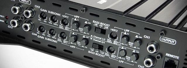
Настройка усилителя для сабвуфера и остальной аудиосистемы может поставить новичка в тупик. Утонченная настройка — дело не простое и требует большого опыта или помощи профессионала.
На этой странице мы разберем основные, базовые настройки — чтобы у вас ничего не сгорело, сабвуфер не пытался отыгрывать скрипку и все было на своих местах.
HPF / LPF (ФВЧ / ФНЧ)
Hight pass filter (HPF), он же фильтр высоких частот (ФВЧ) — отфильтровывает (отсекает) низкие частоты, оставляя высокие.
При настройке сабвуферного усилителя установите регулятор примерно на 20 Hz, чтобы отсечь инфразвук и не тратить энергию, так как вы все равно его не услышите. Для среднечастотных динамиков HPF выставляется в районе 80 Hz, чтобы убрать диапазон низких частот, для которого динамик не предназначен и не сможет его отыграть. Если у вас выделены отдельные каналы или даже отдельный усилитель для твиттеров (пищалок) — HPF выставляется в районе 3000 — 5000 Hz в зависимости от модели, что бы не спалить их.
Все приведенные цифры являются примерными, для получения более точных и безопасных значений изучите характеристики ваших динамиков!
HPF и LPF (полезная статья —(АЧХ) Амплитудно-частотная характеристика)
Low pass filter (LPF), он же фильтр низких частот (ФНЧ) — противоположен HPF и срезает верхние частоты, оставляя нижние.
Для сабвуферов устанавливается в районе 50-80 Hz в зависимости от типа оформления (ЗЯ, ФИ, и т.п.), чтобы отсечь частоты, для которых сабвуфер не предназначен. Аналогично и со среднечастотниками, для них режьте в районе 1400-1600 Hz.
Если есть возможность, то можно ограничить твиттеры на 20 000 Hz, но это не обязательно.
Gain \ Level
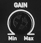
Gain (чувствительность) часто путают с громкостью, но это не совсем правильно.
Gain (гейн) — это регулировка входной чувствительности усилителя для согласования с магнитолой. Но не будем забираться в дебри и рассмотрим эту настройку с точки зрения полезной для пользователя.
Иногда значение Вольт (V) указанное на регуляторе может ввести в заблуждение. Дело в том, что чувствительность измеряется в Вольтах. Чем меньше V — тем выше чувствительность — тем громче будет играть динамик и наоборот.
Для начала будет полезно посмотреть понятое видео про то, как работает гейн на усилителе:
Настройка гейна на слух (1 способ)
Имея хорошее сабовое звено, не пользуйтесь эквалайзером и различными басовыми улучшайзерами, забудьте про bassboost на усилителе — поэтому перед настройкой гейна проверьте чтобы все это было отключено!
Установите регулятор на минимум и включите музыку, которую вы обычно слушаете. Прибавляйте громкость магнитолы на 3/4 от максимума, услышав искажения в звучании саба раньше — остановитесь и убавьте громкость на пару делений. Переходите к усилителю. Попросите помощника медленно прибавлять регулятор гейна до появления новых искажений, а услышав их, остановите вращение и убавьте на 10 %.
Настройка гейна на слух (2 способ)
Если вы не доверяете своему слуху и боитесь во время не услышать изменения, тогда воспользуйтесь более точным способом — с помощью синусов.
Если вы настраиваете сабвуфер, то используйте 40 Гц, в случае если ваш корпус настроен выше 40 Гц или у вас закрытый ящик, тогда берите 50 Гц, (скачать синусы в разделе Загрузки). Для настройки гейна для усилителя мидбаса возьмите 315 Гц.
Синус или тон (в нашем случае) — тоновый сигнал определенной частоты, изменения в звучании которого вы легко услышите
Установите гейн на минимум, включите ваш синус и прибавляйте громкость магнитолы. При изменении звучания тонового сигнала остановитесь и убавьте на пару делений (выставьте ограничение максимальной громкости на это значение, если в вашей магнитоле есть такая функция). Переходите к усилителю. Аналогично первому способу прибавляйте гейн. При изменении звучания остановитесь и убавьте на 10%.
Настройка гейна с помощью мультиметра или осциллографа
Настройка уровня гейна с помощью приборов является грамотным и точным согласованием. При этом не напрягается ни динамик ни ваши уши. Подробно о такой настройке показано в видео на нашем Ютуб канале:
Обратите внимание, что при настройке с помощью мультиметра вы должны быть уверены в мощности, заявленной производителем усилителя.
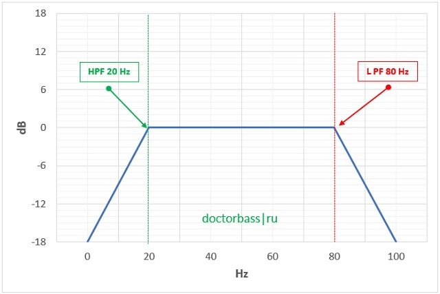
Subsonic

Subsonic — это тот же фильтр высоких частот (HPF) на сабовых усилителях (часто на моноблоках) — отрезает инфразвук. Устанавливайте его по умолчанию примерно на 20-25 Hz. При углубленной настройке, сабсоник выставляется для предотвращения чрезмерного хода диффузора. Поочередно включаются синусы ниже частоты настройки корпуса сабвуфера и по наблюдению за величиной хода диффузора выбирается нужное значение.
Bassboost
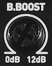
Bassboost — повышает громкость на определенной частоте, как правило это 40-45 Hz. При использовании басбуста шанс спалить сабвуфер резко повышается, так как клипп наступает значительно раньше. В большинстве случаев bassboost не нужен и если вы новичок, то просто примите правило «Басбуст лучше не крутить!»
Опытными людьми он может использоваться для увеличения полки АЧХ, чтобы вытянуть провалы в определенных частотах, но это уже глубокие настройки, на сайте про это есть отдельный материал — Bass Boost — как его настраивать и чем он опасен.
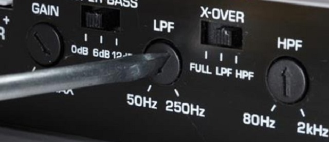
X-over
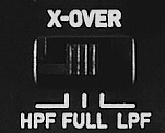
X-over — переключатель фильтров. Присутствует в случае, когда у усилителя не предусмотрена регулировка для каждого фильтра в отдельности. HPF — режет снизу, LPF — режет сверху, Full / Flat — фильтры отключены.
Регулятор фазы (Phase)
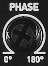
Регулятор фазы — является частью углубленной настройки — меняет фазу динамика. Бывает фиксированный переключатель 0 / 180° и регулятор 0° — 180°. Читайте отдельную тему: Фаза сабвуфера — правильная настройка.
Master/Slave

Этот переключатель используется при мостовом подключения моноблоков. Master устанавливается на усилителе, к которому подходят RCA («тюльпаны») от магнитолы, Slave ставится на подсоединяемом моноблоке.
Видео

Читать еще:
Нажмите кнопку, чтобы поделиться материалом:
Музыка Новости Общение
Подписывайся !
Присоединяйся![]()
Low pass filter
A low pass filter is a frequency filter that allows (passes) frequency below a certain cutoff frequency and disallows (stops) the frequencies above that cutoff frequency.
An example low pass filter and sound sample
See Orinj Low pass filter to hear a sound sample before and after a low pass filter.
An ideal low pass filter
An ideal low pass filter is one that passes all low frequencies – below the cutoff frequency – with unchanged amplitude and one that completely stops all high frequencies. The amplitudes of the low frequencies in the output signal will be 100% of the amplitude of the same frequencies in the input signal. The amplitudes of the high frequencies in the output signal will be zero, independently of what the amplitudes of those frequencies may be in the input signal.
The following is a graph of the magnitude response of an ideal low pass filter with some cutoff frequency.
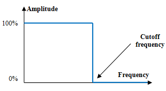
All frequencies below the cutoff frequency remain at their original amplitude. All frequencies above the cutoff frequency are completely removed.
An example finite impulse response (FIR) digital low pass filter
A typical digital finite impulse response filter a(k) computes the output signal y(n) from the input signal x(n) with the following weighted average formula.
A good low pass filter a(k) is
where fs is the sampling frequency, N is the length of the filter (the number of items in the weighted sum), and fc is the cutoff frequency.
If, for example, fs = 2000 Hz, fc = 40 Hz, and N = 201, the magnitude response of the filter will be as in the graph below.
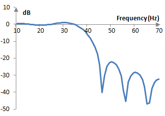
The magnitude response of this filter is not ideal. This said, the filter preserves the amplitudes of frequencies below 40 Hz almost unchanged and attenuates frequencies above 40 Hz. It is thus a low pass filter with a cutoff frequency of 40 Hz.
An example infinite impulse response (IIR) digital low pass filter
The following computation of the output signal y(n) from the input signal x(n) is an example of an impulse invariant second order low pass Butterworth filter
$$y(n)=0.22853 \, x(n-1)+1.19249 \, y(n-1)-0.42804 \, y(n-2)$$
with normalized cutoff frequency ωc = 0.6 (actual cutoff frequency equal to ωc * fs / (2π)). This filter has the transfer function
Given a sampling frequency of, for example, fs = 2000 Hz, the cutoff frequency of this filter becomes 0.6 * 2000 / (2π) = 191 Hz, and the corresponding magnitude response becomes as follows.
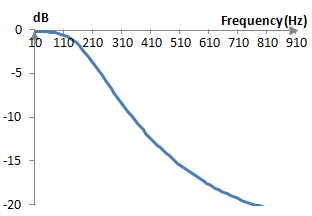
This filter preserves somewhat the amplitude of frequencies below 191 Hz and decreases the amplitudes of frequencies above 191 Hz. Although this is also not an ideal low pass filter, it is a practical low pass filter with cutoff frequency 191 Hz.
Deriving the FIR low pass filter
The desired magnitude response of an ideal low pass filter could be written as follows.
This is an ideal magnitude response of some low pass filter with normalized cutoff frequency fc / fs. By the Nyquist-Shannon sampling theorem fc / fs < 1/2. Using a magnitude response that is symmetric around zero and includes negative frequencies is beneficial, since it allows the inverse Fourier transform below to produce a filter with real valued and not complex valued coefficients.
Denote F = fc / fs. The inverse Fourier transform of the ideal magnitude repose is
The function sin(t) / t is the function sinc(t) and so FIR filters are occasionally called sinc functions. The sinc function in the equation above has ever increasing oscillations until t = 0, at which point it is a(0) = 2 F, after which it has ever decreasing oscillations. To create a discrete time filter, we will sample this continuous time function between -1 and 1 at the sampling frequency.
We then pick a discrete filter of length N from the middle N points of the sampled a(k) and shift it to the right by (N – 1) / 2. This would produce the finite impulse response low pass filter above. In the middle of the filter, at k = (N – 1) / 2, we use L’Hopital’s rule, which states that if the limits of the numerator and denominator are zero and the limits of the derivatives exist, the limit of the ratio is equal to the ratio of the limits of the derivatives.
An alternative derivation
We use the fact that applying a FIR filters to an input signals is simply a convolution of the filter with the signal. The convolution of a cosine and a sine functions of integer frequencies n1 and n2 produces zero, if the two integer frequencies are different, and something other than zero, if n1 = n2.
where one of the simple wave functions in the convolution above is restricted to an interval of unit time and is zero outside of that interval. The result is similar for two cosine and two sine functions. In other words, the convolution of a signal with a properly bound simple cosine or a sine wave would return that same wave in the signal, if the wave exists, and will return zero otherwise. This means that we can design a filter by summing up all simple waves that we want the filter to preserve.
Since we are summing integer frequencies, we can use the following identity, known as the Dirichlet kernel.
We note that the convolution of two simple waves with the same frequency produces the same wave, but with amplitude scaled by fs / 2. Thus, we scale the filter by 2 / fs. We also note that the filter above cannot be computed at k = 0, since the sine in the denominator would produce zero. We use L’Hopital’s rule again. We also center the filter so that its peak is in the middle.
Last but not least, this filter is simply too long. Every output sample produced with this filter would require fs computations. We would prefer a shorter filter of N points.
This formula is an approximation of the first formula above. At fs = 2000 Hz, N = 101, and fc = 40 Hz, for example, the magnitude response of the first filter above (blue) and the filter here (red) are almost identical.
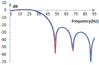
The second filter is, in essence, derived using the discrete Fourier transform and is hence less precise.
Deriving the infinite impulse response low pass filter
IIR low pass filters are also typically derived from their desired magnitude response. For an example of how IIR low pass filters are derived, see the topic Butterworth filter.
Что такое HPF, LPF ?

Настройка усилителя для сабвуфера и остальной аудиосистемы может поставить новичка в тупик. Утонченная настройка — дело не простое и требует большого опыта или помощи профессионала.
Сегодня мы разберем основные, базовые настройки — чтобы у вас ничего не сгорело, сабвуфер не пытался отыгрывать скрипку и все было на своих местах.
HPF / LPF (ФВЧ / ФНЧ)

Hight pass filter (HPF), он же фильтр высоких частот (ФВЧ) — отфильтровывает (отсекает) низкие частоты, оставляя высокие.
При настройке сабвуферного усилителя установите регулятор примерно на 20 Hz, чтобы отсечь инфразвук и не тратить энергию, так как вы все равно его не услышите. Для среднечастотных динамиков HPF выставляется в районе 80 Hz, чтобы убрать диапазон низких частот, для которого динамик не предназначен и не сможет его отыграть. Если у вас выделены отдельные каналы или даже отдельный усилитель для твиттеров (пищалок) — HPF выставляется в районе 3000 — 5000 Hz в зависимости от модели, что бы не спалить их.
*Все приведенные цифры являются примерными, для получения более точных и безопасных значений изучите характеристики ваших динамиков!

Low pass filter (LPF), он же фильтр низких частот (ФНЧ) — противоположен HPF и срезает верхние частоты, оставляя нижние.
Для сабвуферов устанавливается в районе 50-80 Hz в зависимости от типа оформления (ЗЯ, ФИ, и т.п.), чтобы отсечь частоты, для которых сабвуфер не предназначен. Аналогично и со среднечастотниками, для них режьте в районе 1400-1600 Hz.
Если есть возможность, то можно ограничить твиттеры на 20 000 Hz, но это не обязательно.