
Когда земли должны быть разделенными?
Куда я должен подключать земли импульсных регуляторов?
Ответ:
Что делать с аналоговой землей (AGND) и силовой землей (PGND) микросхемы импульсного регулятора? Этот вопрос задают многие разработчики импульсных источников питания. Некоторые из них привыкли иметь дело с цифровой и аналоговой землей, однако, когда дело доходит до силовой земли, они нередко теряются. Тогда они просто копируют разводку платы, рекомендованную для выбранной микросхемы регулятора, и забывают об этой проблеме.


PGND – это точка заземления, через которую протекают более сильные импульсные токи. В зависимости от топологии импульсного регулятора, это может быть током мощного внутреннего транзистора или импульсным током выходного драйвера внешнего транзистора. Это особенно актуально в случае контроллеров импульсных преобразователей, например, с внешними силовыми ключами.
AGND, называемая иногда SGND (signal ground – сигнальная земля), – это заземление, которое, как правило, используют в качестве опорного уровня другие, обычно очень «тихие» сигналы. К таким сигналам относится, в частности, напряжение внутреннего опорного источника, необходимое для стабилизации выходного напряжения. Сигналы разрешения и управления мягким запуском также привязаны к AGND.
Существуют два различных технических подхода и, соответственно, разные мнения экспертов относительно подключения этих земляных соединений.
Один из подходов состоит в том, чтобы контакты AGND и PGND микросхемы импульсного регулятора соединить друг с другом возле соответствующих выводов. Это поддерживает смещение напряжения между двумя выводами относительно низким, защищая микросхему импульсного регулятора от помех, и даже от возможных повреждений. Все земли схемы и земляной слой печатной платы, если он существует, должны звездообразно сходится в эту общую точку. Пример реализации такого подхода показан на Рисунке 1. На нем изображена разводка печатной платы для 10-амперного микромодуля понижающего преобразователя LTM4600. Отдельные земли печатной платы соединены вблизи друг друга (см. синий овал на Рисунке 1). Определенное разделение PGND и AGND происходит уже на кристалле микросхемы из-за паразитной индуктивности соответствующих проводов, соединяющих кристалл с корпусом, а также индуктивности связанных с ними выводов, что приводит к небольшим взаимным помехам между цепями на кристалле.
| Рисунок 1. | Локальное соединение PGND и AGND прямо на контактных площадках. |
Другой подход предполагает дополнительное разделение AGND и PGND на плате на два разных слоя, соединенных друг с другом в одной точке. Благодаря этому соединению сигналы помехи (напряжение смещения) локализуются в основном в области PGND, в то время как напряжение в области AGND остается очень спокойным и очень хорошо отделенным от PGND. Однако недостатком этого метода является то, что, в зависимости от скорости переходных процессов и силы тока, на соответствующих выводах может происходить значительное смещение напряжения между PGND и AGND. Это может стать причиной неправильной работы, или даже повреждения микросхемы импульсного регулятора. Реализация такого подхода показана на Рисунке 2 на примере микросхемы 6-амперного импульсного понижающего регулятора ADP2386.
| Рисунок 2. | Разделенные AGND и PGND, соединенные под земляным основанием корпуса микросхемы через переходные отверстия. |
Вопрос заземления сводится к компромиссу между строгим разделением для минимизации шумов и помех и риском появления смещений напряжения между двумя землями, воздействующих на кристалл микросхемы и нарушающих ее функционирование. Правильное решение в отношении этого компромисса в значительной степени зависит от конструкции микросхемы, включая крутизну фронтов, уровни мощности, паразитные индуктивности внутренних проводов и корпуса, а также риск защелкивания каждой микросхемы.
Заключение
Ответ на вопрос о том, как обходиться с землями AGND и PGND, не так прост. Вот почему дискуссии на эту тему все еще продолжаются. В самом начале я упомянул о том, что многие разработчики импульсных регуляторов используют примеры разводки платы и подключения земель, предоставленные разработчиком микросхем. Это разумно, поскольку, как правило, у вас есть основания предполагать, что производитель проверил соответствующую микросхему в такой конфигурации. Из примеров на Рисунках 1 и 2 также можно видеть, что расположение соответствующих выводов микросхем хорошо подходит как для локального соединения земель возле выводов AGND и PGND, так и для раздельного заземления.
Разумеется, производитель микросхемы может ошибиться при проектировании примеров схем. Вот почему хорошо иметь дополнительную информацию об основных подходах.
Pgnd что это такое
Универсальный англо-русский словарь . Академик.ру . 2011 .
Смотреть что такое «PGND» в других словарях:
EF-Bajonett — Beim Canon EF Bajonett handelt es sich um den aktuellen Objektivbajonett Anschluss für Canon Kleinbild Spiegelreflexkameras der Canon EOS Reihe. Die Bezeichnung EF bedeutet Electro Focus, und das Bajonett kommt, von einer unbedeutenden Ausnahme… … Deutsch Wikipedia
Yoo (Korean name) — Infobox Korean name title=Yu (Ryu) hangul=유 also 류 hanja=linktext|lim=, |柳|劉|兪|庾 rr=Yu also Ryu mr=Yu also Ryu Yoo, also often spelled Ryu or Yu, is a common Korean family name. As of 2000, there were about 1.04 million people by this name living … Wikipedia
Digital Media Port — The Digital Media Port (DMP or DMPort) is an interface for analog audio and video signal and digital control that Sony has started to propose on its A/V products in 2007[1]. As of January 2009, Sony seems to be the only manufacturer proposing… … Wikipedia
What is GND in a Circuit?

What is GND in a circuit? During the PCB Layout routing process, engineers are faced with different GND handling. Why? In the circuit principle design stage, in order to reduce mutual interference between circuits, engineers generally introduce different GND grounds as 0V reference points for different functional circuits, forming different current loops.
Classification of GND
1 Analog ground AGND
Analog ground AGND is mainly used in the analog circuit part, such as the ADC acquisition circuit of analog sensors, operation amplification proportional circuit, etc.
In these analog circuits, because the signal is analog and weak, it is easily affected by high currents from other circuits. If not distinguished, the large current will produce a large voltage drop in the analog circuit, which will make the analog signal distorted and may seriously cause the analog circuit function to fail.
2 Digital ground DGND
Digital ground DGND, obviously relative to analog ground AGND, is mainly used in digital circuits, such as key detection circuits, USB communication circuits, microcontroller circuits, etc.
The reason why digital ground DGND is set up is that digital circuits have a common feature. They are all discrete open light signals, only the number "0" and the number "1" to distinguish, as shown in the figure below.
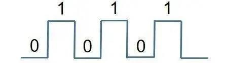
During the transition from the digital "0" voltage to the digital "1" voltage, or the transition from the digital "1" voltage to the digital "0" voltage, the voltage has a change. According to Maxwell's electromagnetic theory, the change A magnetic field is generated around the current, which forms EMC radiation to other circuits.
In order to reduce the EMC radiation impact of the circuit, a separate digital ground DGND must be used so that other circuits are effectively isolated.
3 Power ground PGND
Analog ground AGND or digital ground DGND, are all low power circuits. In high-power circuits, such as motor drive circuits, solenoid valve drive circuits, etc., there is also a separate reference ground, which is called the power ground PGND.
High-power circuits, as the name implies, are relatively large current circuits. Obviously, large currents are likely to cause ground offsets between circuits with different functions, as shown in the figure below.

Once there is a ground shift in the circuit, the original 5V voltage may not be 5V, but 4V. Because the 5V voltage is referred to the GND ground line 0V, if the ground offset causes the GND line to rise from 0V to 1V, then the previous 5V (5V-0V=5V) voltage becomes the current 4V (5V-1V= 4V) again.
4 Power supply GND
Analog ground AGND, and digital ground DGND, and power ground PGND, are all classified as DC ground GND. These different types of ground, finally all come together as a 0V reference ground for the whole circuit, this ground is called power ground GND.
The voltage and current required for all circuits to work come from the power supply. Therefore, the GND of the power supply is the 0V voltage reference point for all circuits.
This is why other types of ground, whether it is analog ground AGND, digital ground DGND, or power ground PGND, all need to be brought together with the power supply ground GND at the end.
5 AC ground CGND
AC ground CGND is generally present in circuit projects containing AC power, such as AC to DC power circuits.
AC-DC power supply circuit is divided into two parts. The front stage of the circuit is the AC part and the backstage of the circuit is the DC part, which forces the formation of two grounds, one for the AC ground and the other for the DC ground.
The AC ground serves as the 0V reference point for the AC portion of the circuit, and the DC ground serves as the 0V reference point for the DC portion of the circuit. Usually, in order to unify a ground GND in a circuit, engineers connect the AC ground to the DC ground through a coupling capacitor or inductor.
6 Earth ground EGND
The safe voltage for the human body is below 36V. Voltages exceeding 36V can cause damage to the human body if applied to the body, which is a common sense safety for engineers in developing and designing circuit project solutions.
In order to enhance the safety factor of the circuit, engineers generally use the earth ground EGND in high-voltage and high-current projects, such as in the circuits of household appliances electric fans, refrigerators, and televisions. The socket with earth ground EGND protection is shown in the picture below.
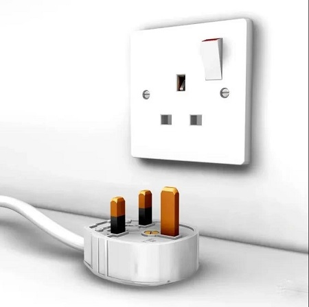
220V AC only needs the fire wire and zero wire. Why socket for household appliances have 3 terminals?
The two of 3 terminals of the socket are used for the 220V fire and zero wires, and the other terminal-the earth ground EGND is to play a protective role.
The earth ground EGND, it is only connected to our earth, to play a high-voltage protection role. It is not involved in the project circuit function.
Therefore, the meaning of EGND and other types of GND circuits are significantly different.
Working principle of GND
How can a ground GND have so many distinctions, and how can a simple circuit problem be made so complicated?
Why is it necessary to introduce so many subdivision of the GND ground function?
Generally, engineers simply named this type of GND ground wire design as GND. There is no distinction in the schematic design process, which makes it difficult to effectively identify the GND ground wires of different circuit functions during PCB layout. They directly and simply connect all GND ground wires together.
Although this is easy to operate, it will lead to a series of problems.
1 Signal crosstalk
If the different functions of the ground GND are directly connected together, high-power circuits through the ground GND, will affect the 0V reference point GND of low-power circuits so that the crosstalk between the signals of different circuits is generated.
2 Signal accuracy
The core indicator of the Analog circuit is the accuracy of the signal. Without accuracy, the analog circuit loses its original functional significance.
The ground CGND of the AC power supply is a sine wave that fluctuates up and down periodically. Its voltage also fluctuates up and down, not always maintained at a constant 0V like the DC ground GND.
Connecting the ground GND of different circuits together, the cyclically changing AC ground CGND will drive the analog circuit ground AGND to change, which will affect the voltage accuracy value of the analog signal.
3 EMC experiment
The weaker the signal is, the weaker the EMC of external electromagnetic radiation is. The stronger the signal is, the stronger the EMC of external electromagnetic radiation is.
If the GND of different circuits are connected together, the GND of the circuit with strong signal directly interferes with the GND of the circuit with weak signal. The consequence is that the EMC with a weak signal becomes the source of strong external EMR, which increases the difficulty of the circuit processing EMC experiment.
4 Circuit reliability
Between circuit systems, the fewer the parts of the signal connection, the stronger the ability of the circuit to operate independently; the more the parts of the signal connection, the weaker the ability of the circuit to operate independently.
If there is no intersection between two circuit systems A and B, it is obvious that the function of circuit system A cannot affect the normal operation of circuit system B. Similarly, the function of circuit system B cannot affect the normal operation of circuit system A.
If the circuit ground wires of different functions are connected together in the circuit system, it is equivalent to increasing a link of interference between the circuits, that is, reducing the reliability of circuit operation.


We are the professional distributor of electronic components, providing a large variety of products to save you a lot of time, effort, and cost with our efficient self-customized service. careful order preparation fast delivery service
Difference between GND and PGND
HI, I m using a SLIC Ag1460. There are two grounds associated with it. A simple GND and a PGND (Power Ground). I want to know that are GND and PGND same or different from each other. What should i do to to connect a pin to PGND.
Timely answer to this is the key for success to my project.
- Mar 26, 2007
- #2
maziaar83
Junior Member level 2
what is pgnd
Hey man!
they are completely different!
do not connect them together! never!
- Mar 26, 2007
- #3
DrWhoF
Advanced Member level 1
I think they have to be connected at one point.
Take a look in this PDF file at PCB layout and circuit diagram:
**broken link removed**
- Mar 26, 2007
- #4
xerxer
Junior Member level 3
i think this relate to kelvi connetion. so you can not connect the two pad in dircect
- Mar 26, 2007
- #5
kevpat
Member level 2
Kashi, You will need to connect the grounds at a star-point usually as close as possible to the power input/output point on your pcb. This should be the only point they connect to stop large pwr GND circulating currents effecting sensitive circuitry connected to your GND plane.
- Mar 27, 2007
- #6
wichayen
Member level 2
As datasheet that posted by DrWhoF.
PGND and GND is the same reference level. So you I think you should connect it together (by star connection).
The reason why they seperate PGND and GND is to avoid noise interference from GND to PGND. usually power circuit is low frequency and digital circuit is high frequency. You can see in datasheet that posted by DrWhoF. The inner layer2,3 of PCB seperate 2 area. because they want to connect PGND and GND only one point (star connection).
- Mar 27, 2007
- #7
kender
Advanced Member level 4
difference -vss and gnd
You should connect GND and PGND at exactly one point on your board (or, may be, one point in your whole instrument). This is called "star ground", or "totem pole ground". You can find a simple diagram of the star ground here