
Усилитель мощности RF — RF power amplifier
А усилитель мощности радиочастоты (Усилитель мощности RF) является разновидностью электронный усилитель что преобразовывает маломощный радиочастота сигнал в сигнал более высокой мощности. Обычно усилители мощности RF управляют антенной передатчик. Цели дизайна часто включают прирост, выходная мощность, полоса пропускания, энергоэффективность, линейность (низкая сжатие сигнала при номинальной мощности), согласование входного и выходного импеданса и тепловыделение.
Содержание
Классы усилителя
Многие современные ВЧ усилители работают в разных режимах, называемых «классами», для достижения различных целей проектирования. Некоторые классы класс А, класс AB, класс B, класс C, которые считаются классами линейных усилителей. В этих классах активное устройство используется в качестве управляемого источника тока. Смещение на входе определяет класс усилителя. Обычный компромисс в конструкции усилителя мощности — это компромисс между эффективностью и линейностью. Ранее названные классы становятся более эффективными, но менее линейными в том порядке, в котором они перечислены. Использование активного устройства в качестве переключателя приводит к повышению эффективности, теоретически до 100%, но меньшей линейности. [1] Среди классов переключения режимов: Класс D, Класс F и класс E. [2] Усилитель класса D не часто используется в ВЧ-приложениях, потому что конечная скорость переключения активных устройств и возможное накопление заряда при насыщении может привести к большому продукту I-V. [1] , что снижает эффективность.
Твердотельные и ламповые усилители
Современные усилители мощности RF используют твердотельные устройства, преимущественно МОП-транзисторы (полевые транзисторы металл-оксид-полупроводник). [3] [4] [5] Первые ВЧ усилители на базе полевых МОП-транзисторов относятся к середине 1960-х годов. [6] Биполярные переходные транзисторы также широко использовались в прошлом, пока не были заменены на силовые МОП-транзисторы, особенно LDMOS транзисторы, как стандартная технология для ВЧ усилителей мощности к 1990-м годам, [3] [5] благодаря превосходным характеристикам ВЧ транзисторов LDMOS. [5]
MOSFET транзисторы и другие современные твердое состояние устройства заменили вакуумные трубки в большинстве электронных устройств, но лампы все еще используются в некоторых передатчиках большой мощности (см. Valve RF усилитель ). Несмотря на механическую прочность, транзисторы электрически хрупкие — они легко повреждаются избыточным напряжением или током. Трубки механически хрупкие, но электрически прочные — они могут выдерживать чрезвычайно высокие электрические перегрузки без ощутимых повреждений.
Приложения
Основные применения усилителя мощности RF включают в себя подключение к другому источнику высокой мощности, управление передающим антенна и захватывающий микроволновая печь резонаторы. Среди этих приложений наиболее известны управляющие антенны передатчика. В передатчик-приемники используются не только для передачи голоса и данных, но и для определения погоды (в виде радар ). [ нужна цитата ]
ВЧ усилители мощности, использующие LDMOS (MOSFET с боковой диффузией) являются наиболее широко используемыми силовые полупроводниковые приборы в беспроводная связь сети, в частности мобильные сети. [7] [8] [5] ВЧ усилители мощности на основе LDMOS широко используются в цифровых мобильных сетях, таких как 2G, 3G, [7] [5] и 4G. [8]
Конструкция широкополосного усилителя
Импеданс трансформации в больших пропускная способность сложно реализовать, поэтому большинство широкополосный усилители используйте выходную нагрузку 50 Ом. Транзистор выходная мощность ограничивается
Метод нагрузочной линии часто используется при разработке усилителей мощности ВЧ. [9]
Сети кабельного телевидения для самых маленьких. Часть 6: Усилители RF-сигнала

В случае, если на доме (или даже в целом квартале) только один оптический приёмник и вся разводка до стояков выполнена коаксиальным кабелем, обязательно требуется усиление сигнала в их начале. В нашей сети применяются в основном устройства фирмы Teleste, поэтому рассказывать буду на их примере, но принципиально оборудование других производителей ничем не отличается и набор функционала для настройки обычно схож.
Минимальное количество настроек имеет модель CXE180M:
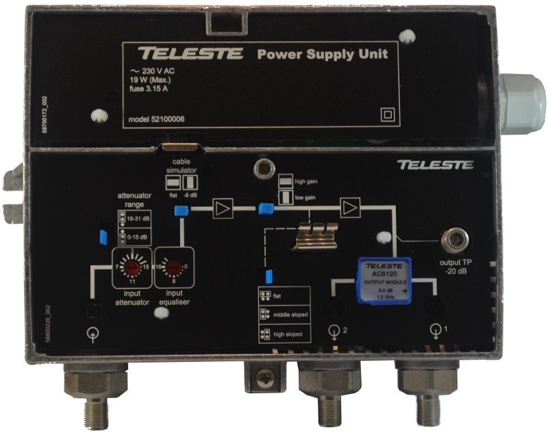
Как вы, вероятно, помните из предыдущих частей у сигнала есть два важных количественных параметра: это уровень и наклон. Именно их и могут помочь поправить настройки усилителя. Начнём по порядку: сразу после входного разъёма находится аттенюатор. Он позволяет уменьшить входной сигнал на величину до 31дБ (при переключении синего джампера в соответствии со схемой диапазон крутилки меняется с 0-15 на 16-31дБ). Это бывает необходимо в случае, если на усилитель приходит сигнал более 70 дБмкВ. Дело в том, что усилительный каскад обеспечивает подъём уровня сигнала на 40 дБ, а на выходе мы должны снять не более 110 дБмкВ (при более высоком уровне резко падает отношение сигнал/шум и эта цифра актуальна для всех широкополосных усилителей и приёмников с встроенным усилителем). Таким образом, если на вход усилителя попадает 80 дБмкВ, например, то на выходе он нам отдаст 120 дБмкВ шума и рассыпающейся цифры. Чтобы этого избежать нужно выставить входной аттенюатор в положение гашения 10дБ.
За аттенюатором мы видим эквалайзер. Он необходим для устранения обратного наклона, если он есть. Достигается это за счёт уменьшения уровня сигнала в зоне низких частот на величину до 20дБ. Стоит обратить внимание, что устранить обратный наклон, подняв уровень верхних частот мы не сможем, только задавить нижние.
Этих двух инструментов бывает достаточно для того, чтобы исправить незначительные отклонения сигнала от нормы. В случае, если это не так, то можно воспользоваться следующими:
Симулятор кабеля, выполненный в виде вставки, которую можно поставить горизонтально или вертикально, как понятно из названия, симулирует включение длинного участка кабеля, на котором должно произойти затухание преимущественно верхних частот диапазона. Это позволяет уменьшить при необходимости прямой наклон, задавив 8дБ в зоне высоких частот. Такое бывает полезно при установке усилителей каскадом на короткой дистанции, например.
После этих манипуляций сигнал проходит первую ступень усилительного каскада, после которой мы видим ещё одну вставку, которая позволяет дополнительно снизить коэффициент усиления. Следующий за ним джампер вновь поможет нам задавить низкие частоты для получения необходимого наклона. Эти две настройки по сути являются аналогом входных аттенюатора и эквалайзера, но работающих со второй ступенью каскада.
На выходе усилительного каскада мы видим тестовый отвод. Это стандартный резьбовой разъём, к которому можно подключить измерительный прибор или телеприёмник для контроля качества выходного сигнала. Не все приборы и практически ни какие телевизоры способны нормально переварить сигнал с уровнем в сто и более дБмкВ, поэтому тестовые отводы на любом оборудовании всегда делаются с затуханием в 20-30дБ от действительной величины на выходе. Это нужно всегда держать в голове, проводя измерения.
Перед выходом установлена ещё одна вставка. На фото усилителя видно, что изображённая на ней стрелка указывает только на правый вывод. И это значит, что в левом сигнала не будет. Такие вставки стоят в этих усилителях «из коробки», а внутри самой коробки в комплекте поставки лежит другая:

Она позволяет задействовать второй вывод, но неизбежно вносит затухание сигнала на величину 4дБ.
Усилитель модели CXE180RF на первый взгляд имеет вдвое больше настроек: 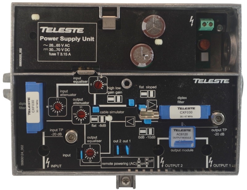
На самом деле всё не так страшно: за исключением небольших отличий здесь всё то же самое, что и в рассмотренном выше.
Во-первых, на входе появился тестовый отвод. Он нужен для контроля сигнала без отключения кабеля от входа усилителя и, соответственно, без перерыва вещания.
Во-вторых, появившиеся диплексные фильтры, а так же аттенюатор и эквалайзер выхода необходимы для настройки каналов прохождения DOCSIS, поэтому в рамках этой статьи скажу лишь, что фильтры отрезают те частоты, которые указаны на них и это может стать проблемой, если в спектре сигнала на этих частотах вещаются ТВ каналы. К счастью, производитель выпускает их с разными значениями и заменить их при необходимости не составляет труда. 
Крутилки же (как и джампер, вносящий затухание в 10дБ) влияют исключительно на обратный канал и никак не способны изменить телевизионный сигнал.
А вот оставшиеся три джампера предлагают нам познакомиться с такой технологией, как удалённое питание.
При проектировании домов зачастую усилители размещаются в таких местах, где могут быть проблемы с подводом электричества от распределительных щитов. Кроме того, каждая пара «вилка-розетка», подразумевающая за собой ещё и автоматический выключатель (который может быть установлен в самом неожиданном месте), представляют собой потенциальную точку отказа. В связи с этим существует возможность питать оборудование прямо по коаксиальному кабелю. Причём, как видно из маркировки на накладке блока питания, это может быть как переменный, так и постоянный ток с весьма широким диапазоном напряжений. Так вот: эти три джампера и включают возможность протекания питающего тока на вход, а так же на каждый из двух выходов по отдельности, если нам нужно запитать следующий усилитель в каскаде. При включении стояка с абонентами напряжение на выход конечно же подавать нельзя!
Я уже упоминал в предыдущей части, что в такой системе используются специальные магистральные ответвители:
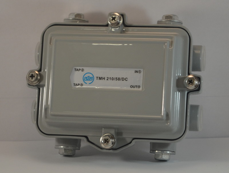
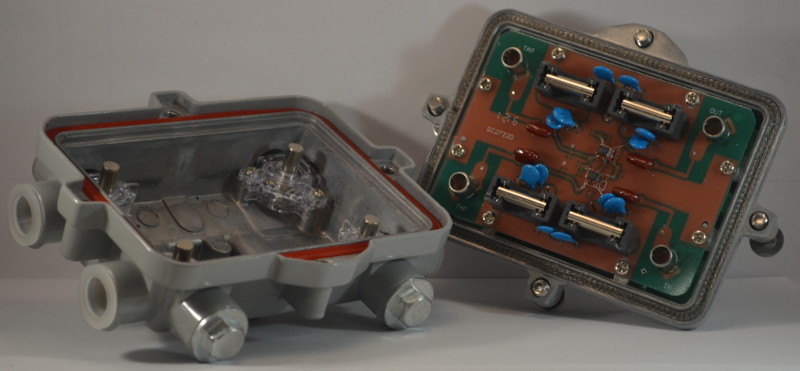
В них используются более крупные и надёжные элементы, а массивный корпус обеспечивает теплоотвод и защиту.
Источником питания в таком случае является блок с встроенным массивным трансформатором: 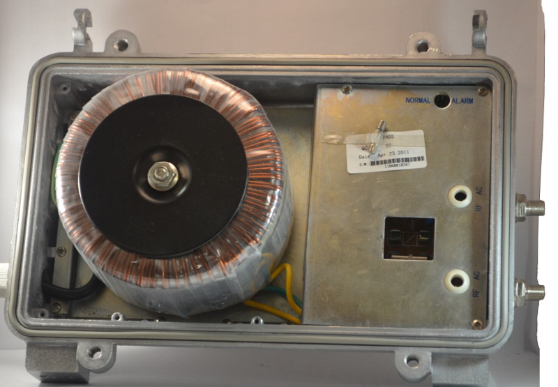
Стоит сказать, что при кажущейся оптимальности схемы дистанционного питания, работающие таким образом усилители реже без последствий переживают аварии энергоснабжения на домах, а при их замене техперсоналу дополнительно приходится искать и отключать питание самого блока, чтобы не работать с кабелями под напряжением и, таким образом, на время замены одного усилителя без сигнала остаётся весь дом. По той же причине на таких усилителях необходим тестовый отвод на входе: иначе пришлось бы работать с кабелем под током.
Было бы интересно узнать от коллег насколько распространены системы с дистанционным питанием, напишите в комментариях, если используете, пожалуйста.
При необходимости подключить большое количество телевизоров внутри квартиры или офиса можно столкнуться с нехваткой уровня после цепочки делителей. В таком случае необходимо устанавливать усилитель на территории абонента, для чего используются небольшие устройства с минимальным количеством настроек и меньшим уровнем усиления.
Например, такой: 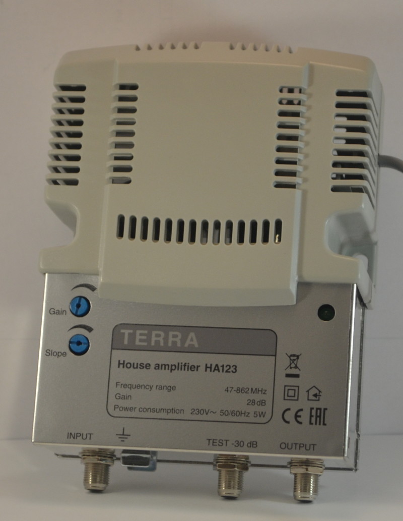
What does an RF Power Amplifier Do?

An RF power amplifier is a crucial component of any wireless transmitter. So the question is What does an RF power amplifier do? The RF signal produced by the instrumentation oscillator circuit in the transmitter’s front-end circuit has very low power and requires several stages of amplification before it can be sent on to the antenna. These stages are the buffer amplifier, the intermediate amplifier, and the final power amplifier. After a sufficient amount of RF power is generated, it may be transmitted via an antenna.
Transmission through matching networks
· A High Power RF Amplifier amplifier is required to provide a high enough RF output power.
· First, the radio frequency signal is generated by the modulator; secondly, the radio frequency amplifier boosts the signal to transmitting power; finally, the antenna transmits the signal through the matching network.
Output power and efficiency are essential parameters for RF power amplifiers. The main focus of RF power amplifier design is on how to maximize output power and efficiency.
Distortion-free amplification
Conventionally, the LC resonant circuit of an RF power amplifier allows for distortion-free amplification of either the fundamental frequency or a specific harmonic. To prevent unwanted interference on other frequencies, the output’s harmonic components should be kept to a minimum. Gain, noise, bandwidth, efficiency, linearity, and other performance factors are among a High Power Amplifier’s most distinguishing features.
The crucial components
· Using these features as the primary criterion for categorization, they can identify the many distinct amplifier kinds, each of which is optimal for a different set of circumstances.
· The size, efficiency, and overall performance of an RF power amplifier are crucial components of any RF transmitter.
The amplifier’s first two stages achieve high efficiency by operating in class-A and class-AB modes, while the third stage achieves the highest possible efficiency by operating in class-C mode.
The applications
An RF amplifier has many applications in the chain of communications. A power amplifier, which is linked to the radio’s antenna in order to boost the signal before it is sent, is used in this context. With a low-noise amplifier, a distorted signal may be amplified without producing much more noise. In the dynamic mobile channel, it serves as a variable Gain Amplifier, allowing for more successful data recovery at the receiving end.
The ultimate output
· By using external components, RF Amplifier Design may fine-tune the input and output matched circuits to achieve optimal power and efficiency at any specified operating frequency.
· The RF power amplifier in the transmitter may have an output power range from a few milliwatts (mW) to several kilowatts (kW), however this is the ultimate power amplifier’s output.
If you want a lot of power coming out of your final stage, you need to make sure the excitation power is very high.
Long-distance broadcasting
For long-distance broadcasting through shortwave radio, which relies on ionospheric reflection, a narrow beam of energy is often directed upward at an angle of 5° to 10° from the horizontal. The compactness, low power consumption, cooling, and high output power of RF amplifiers and RF amplifier design systems find widespread use in jamming, communication, test, and radar systems.
Cutting-edge technologies
· Using cutting-edge GaN, and bipolar device technologies, these large power microwave amplifiers are able to achieve high efficiency throughout an ultra-wide operating band, in addition to great durability and robustness.
· Unless in a frequency-modulated system, audio transmissions do not need wide-band radio-frequency amplifiers.
Broadcast audio with amplitude-modulated transmissions requires a radio-frequency bandwidth of 10 kilohertz, albeit this is often only possible on medium-wave frequencies.
Frequency-modulated audio
Frequency-modulated audio of high quality requires a bandwidth of around 100 kilohertz. Very few challenges arise during the construction of Radio Frequency Amplifier, and distortion issues may be addressed by feeding the amplifier’s output back into its input via a negative feedback loop. The selectivity and gain of tuneable radio frequency amplifiers varies over the tuning range.
Setting tuning frequency
At the greatest tuning frequency, instability may be a problem, and when capacitance is reduced, selectivity and gain both tend to rise. These problems are absent in intermediate-frequency amplifiers due to the set tuning frequency. High linearity, high efficiency, low noise, and low power consumption are only some of the features of the RF amplifier modules and systems. Solid-state devices provide the basis of all Microwave solid-state RF power amplifier modules and systems, which offer several benefits to consumers.
The uses for RF Amplifiers are many
· To increase the strength of a signal at a given radio frequency, an RF Power Amplifiers is necessary.
· Including low phase noise into an amplifier’s design is essential. As a medium wave’s wavelength is about 300 meters, a high-power transmitter may employ a vertical transmission mast or self-supporting tower between 150 and 210 meters in height.
Ideally, a receiving antenna of equivalent height would be installed, but this is not feasible.
Vertical shortwave antenna
Both the transmitting and receiving antennas must be in the same vertical or horizontal orientation depending on whether the transmission or reception is taking place. Since the plane of the electromagnetic field of shortwaves may be bent as they travel through the ionosphere, a vertical shortwave antenna may be able to pick up a decent signal from a horizontal transmitting antenna, this rule applies to all radio frequencies except shortwaves.
What is RF Power Amplifier?

The radio frequency power amplifier (RF PA) is a critical component of many wireless transmitters, and its significance is self-evident. The power of the RF signal generated by the modulation oscillator circuit in the pre-stage circuit of the transmitter is very low, and it must go through a series of amplification stages (buffer stage, intermediate amplification stage, final power amplification stage) to obtain sufficient RF power before it can be fed Radiate to the antenna. A radio frequency power amplifier is required to obtain sufficient radio frequency output power. The radiofrequency modulated signal is amplified to adequate strength by the RF PA once it is generated by the modulator and then sent by the antenna through the matching network.
2. Principle
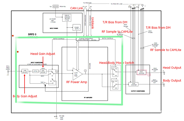
Take a close look at the green label. First, the RF signal enters from the left, goes through a gain, gains the "body signal," and then separates the "head signal" from the "body signal" and switches it through a switch. This is referred to as "first level amplification." It can be interpreted as "extensive" by anyone.
After that, we went to an RF power AMP amplifier. This mark is required knowledge for students who have studied analog circuits. The RF signal is amplified with a power of 10KW in this part, which we can call "secondary amplification."
Finally, we utilize a switch to separate the "BODY / HEAD" RF outputs. The primary function of this switch is to control when "head output" and "body output" occur. I may confidently state that the two channels will not operate at the same time.
3. Classification
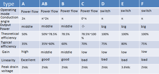
According to different working conditions, power amplifiers are classified as follows:
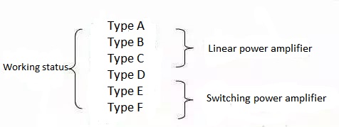
Traditional linear power amplifiers have a very high operating frequency, but their frequency band is relatively restricted. A frequency selective network is commonly used as a load loop in radio frequency power amplifiers. According to the current conduction angle, radio frequency power amplifiers can be separated into three types of working states: A (A), B (B), and C (C). The class A amplifier current has a 360° conduction angle, which is ideal for low-power amplification of tiny signals. The class B amplifier current has a conduction angle of 180°, while the class C amplifier current has a conduction angle of less than 180°. Both Class B and Class C are ideal for high-power working circumstances, with Class C working conditions having the maximum output power and efficiency of the three. Most RF power amplifiers operate in Class C, but Class C amplifiers have too much current waveform distortion and can only be used to boost the resonant power of the load via a tuning loop. The loop current and voltage are still close to sinusoidal waveforms, and the distortion is low, thanks to the tuning loop's filtering capacity.
Changing the Mode Electronic gadgets work in a switching condition thanks to PA and SMPA. Class D (D) and class E (E) amplifiers are both often used. Class D amplifiers have a higher efficiency than class C amplifiers. In switch mode, SMPA drives active transistors. The transistors are either on or off when they are in use. Because the voltage and current time-domain waveforms do not overlap, the DC power consumption is nil, and the optimal efficiency can reach 100%.
Traditional linear power amplifiers have great gain and linearity but low efficiency, whereas switching power amplifiers offer excellent efficiency but poor linearity. Details can be found in the table below:
The amplifier's job is to amplify and output the stuff it receives. The content of input and output, which we refer to as "signal," is frequently expressed in terms of voltage or power. The "contribution" of a "system" like an amplifier is to boost what it "absorbs" to a specific level and "output" it to the outside world. If the amplifier can function well, it will be able to give more, reflecting its own "worth." If the amplifier has certain faults, it will no longer be able to offer any "contribution" after starting to function or working for a period of time, but there may be some unanticipated "oscillation," which is still the amplifier for the outside world. It's all a disaster in and of itself.
Ⅱ. Circuit composition
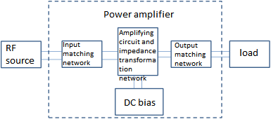
There are different types of amplifiers. To simplify, the amplifier circuit can be composed of the following parts: transistors, bias and stabilization circuits, and input and output matching circuits.
1-1. Transistor
Transistors come in a variety of shapes and sizes, as well as the invention of transistors with multiple architectures. A transistor's job is essentially that of a regulated current or voltage source, and its operating mechanism is to convert the direct current energy content into a "useful" output. DC energy is captured from the environment, consumed by transistors, and transformed into useable components. Different transistors have different "capabilities," such as their ability to tolerate power, which is owing to their different ability to obtain DC energy; for example, their response speed varies, determining how wide and high they can work. On the frequency range, for example, the input and output impedances are different, as is the ability to respond to the outside, which impacts the difficulty of matching it.
1-2. Bias circuit and stabilization circuit
Although bias and stabilization circuits are two distinct circuits, they can be described together because they are often difficult to identify and have similar design aims.
The transistor must operate under specified bias circumstances, which we refer to as the static operating point. The transistor and its own "positioning" are built on this foundation. Each transistor has a unique location that determines its functioning mode. Varying positioning also results in different performances. Some positioning points have small fluctuations, which are suitable for small signal work; some positioning points have large fluctuations, which are suitable for high-power output; some positioning points require less demand, pure release, which is suitable for low-noise work; some positioning points, transistors have large fluctuations, which are suitable for high-power output; some positioning points, transistors have large fluctuations, which are suitable for high-power output; some positioning points, transistors have large fluctuations, which are suitable for high-power output; some positioning points, In the on-off stage, I'm always floating between saturation and cut-off. The foundation for normal operation is an adequate bias point. The bias circuit has a higher impact on the circuit performance when designing a broadband power amplifier or when the operating frequency is high. The bias circuit should now be regarded a component of the matching circuit.
Passive and active bias networks are the two types of bias networks. To supply sufficient operating voltage and current for the transistors, passive networks (also known as self-biased networks) are often made up of resistor networks. Its primary flaw is that it is extremely susceptible to changes in transistor settings and has poor temperature stability. The active bias network may improve the stability of the static operating point as well as temperature stability, but it comes with several drawbacks, including increased circuit size, increased circuit layout difficulties, and increased power consumption.
Because the transistor must have the stabilization circuit as part of itself before contacting the outside world, the stabilization circuit must come before the matching circuit. The transistor with the stabilizing circuit is a "new" transistor in the eyes of the outside world. It attained stability by making certain "sacrifices." The circuit stabilization mechanism can assure the transistor's smooth and steady operation.
1-3. input and output matching circuit
The matching circuit's objective is to select an appropriate approach. Accepting and outputting the entire signal is the way to go for transistors that want to deliver more gain. This means that communication between distinct transistors is smoother thanks to the matching circuit's interface. The matching circuit is not merely a "complete acceptance" design strategy for different types of amplifiers. Some short tubes with a shallow foundation and a small DC are more inclined to accept a certain block in order to improve noise performance. They cannot, however, block too much; else, their contribution will be harmed. You must be cautious while outputting from some huge power tubes because they are more unstable, although at the same time, a certain amount of retention allows them to exert more "undistorted" energy.
L matching, matching, and T matching are examples of common impedance matching networks. L matching is unique in that it has a simple structure and only two degrees of freedom, L and C. The network's Q value (bandwidth) is obtained once the impedance conversion ratio and resonance frequency have been measured. One of the benefits of the -shaped matching network is that it can absorb any parasitic capacitance that is linked to it. Because it is dominant in many practical circumstances, this leads to the general application of the -shaped matching network. The capacitance is the position's parasitic element. T-shaped symmetry. T-shaped matching can be used to absorb parasitic parameters into the network when the parasitic characteristics of the power supply and load terminals are primarily inductive.
Ⅲ. How to choose the right RF amplifier?
When choosing an RF amplifier for a certain application, factors including gain, noise, bandwidth, and efficiency should be taken into account.
This article will go over the most popular RF amplifiers and discuss how gain, noise, bandwidth, efficiency, and other functional properties influence amplifier selection for diverse applications.
RF amplifiers come in a variety of shapes and sizes to suit a variety of applications. However, choosing the proper RF amplifier for the desired application is difficult due to the large number of RF amplifiers available. Although gain is a significant attribute of practically all RF amplifiers, it is not the only criterion to consider when selecting a device, and in many circumstances, it is not even the most essential.
Gain is the ratio of output power to input power that determines how much signal boost the amplifier can deliver (in dB). It is often specified for the linear mode of the amplifier (in which the change in output power is proportional to the change in input power) (see Figure 1). If you keep increasing the strength of the RF amplifier's input signal, the device will go into non-linear mode and emit spurious frequency components. Harmonics and intermodulation products (HD2, HD3, IMD2, and IMD3 in Figure 2), which reflect the intermodulation distortion (IMD) that emerges at the RF amplifier's output, are among the interference components. The RF amplifier's ability to withstand varying input power levels without severe distortion is reflected in its linearity performance, which can be expressed by a variety of characteristics (see Figure 1), including:
The output power when the system gain is lowered by 1 dB is known as the output 1 dB compression point (OP1dB).
Saturated output power (PSAT) is the output power at which changes in the input power have no effect on the output power.
The input (IIP2, IIP3) and output (OIP2, OIP3) signal power levels are represented by the second-order intermodulation point (IP2) and third-order intermodulation point (IP3), respectively. The relevant erroneous components are present at these locations. The strength will equal that of the fundamental wave component.
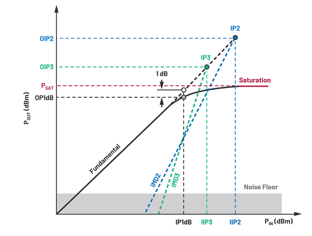
Figure 1. The Output Power Characteristics of the RF Power Amplifier and its Nonlinear Parameters
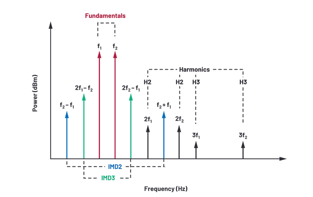
Figure 2. Harmonic and Intermodulation Products.
Ⅳ. What is the Difference Between Different RF Power Amplifiers?
Although the gain is the primary purpose of an RF amplifier, linearity and other properties play a significant role in RF amplifier selection. In fact, selecting an RF amplifier type always necessitates a compromise between many design criteria. Here's a quick guide on picking the proper type of RF amplifier for your application.
Amplifier with low noise
In receiver applications, low noise amplifiers (LNA) are frequently employed to amplify weak signals at the front end of the signal chain that interface with the antenna. When performing this duty, this sort of RF amplifier is designed to introduce the least amount of noise into the signal. Noise minimization is especially critical in the initial few stages of the signal chain, because these stages have the biggest impact on the overall noise figure of the system.
Low phase noise amplifier
Low phase noise amplifiers have very little excess phase noise, making them ideal for RF transmission chains that require great signal integrity. Close-in carrier noise exhibited as jitter is characterized by minor fluctuations in the phase of the signal in the time domain, and is referred to as phase noise. As a result, the low phase noise amplifier is well suited for usage in the LO network with high-speed clock and high-performance PLL frequency synthesizers.
Power amplifier
The power amplifier (PA) is designed for high-power applications, such as transmitter systems, and is optimized for power handling performance. These amplifiers typically have high OP1dB or PSAT characteristics and excellent efficiency, allowing for little heat dissipation.
High linearity amplifier
Over a large input power range, the high linearity amplifier is employed to give a high third-order intermodulation point with a very low spurious level. For communication applications that use complicated modulated signals, this type of device is a popular choice. RF amplifiers that can tolerate high crest factors with minimum signal distortion while retaining a low bit error rate are required for such applications.
Variable gain amplifier
Variable gain amplifiers (VGAs) are utilized in applications that demand variable gain modification to adapt to variations in signal level. VGA accomplishes this by allowing for customizable gain. With a digitally controlled VGA, the gain can be altered gradually, or it can be changed continuously with an analog controlled VGA. Automatic gain control (AGC) and compensation for gain drift induced by temperature or characteristic changes in other components are common applications for this type of amplifier.
Broadband amplifier
Broadband amplifiers may offer medium gain over a wide frequency range (typically many octaves), which is useful for a variety of broadband applications. Large gain-bandwidth products are provided at the expense of mediocre efficiency and noise performance in these amplifiers.
Obtain a block
Gain modules, a broad category of RF amplifiers that can encompass many frequencies, bandwidths, gains, and output power levels, can also be used in other general-purpose RF applications. The gain response of these amplifiers is usually flat, and the return loss is low. Its design frequently contains matching and bias circuits, allowing it to be integrated into the signal chain with few external components, reducing labor time.
The output power and efficiency of RF power amplifiers are the most important technical indicators. The fundamental design goals of RF power amplifiers are to improve output power and efficiency. An LC resonant circuit can be used to choose the fundamental frequency or a specific harmonic in a radio frequency power amplifier to provide distortionless amplification. In addition, to avoid interference with other channels, the harmonic components in the output should be as reduced as feasible.


We are the professional distributor of electronic components, providing a large variety of products to save you a lot of time, effort, and cost with our efficient self-customized service. careful order preparation fast delivery service