
Interfacing Arduino Mega using LabVIEW
This post is about Interfacing Arduino Mega using LabVIEW. It was originally posted here as a part of element14’s RoadTest. I thank element14 for sending me the review unit.
Evaluation Type: Independent Products
Was everything in the box required?: Yes
Comparable Products/Other parts you considered: Arduino due , Raspberry Pi
What were the biggest problems encountered?: When arduino ide is running, other programs such as Labview cant programme the mega.This is true in general of all arduino device.The only solution i found was to close arduino ide , log off and then log back in.
Detailed Review:
Arduino Mega the big brother of Arduino Uno has 54 digital I/O pins, 16 analogue inputs. That’s a whopping difference of 40 digital and 10 analogue pins.the closest to it in the Arduino family is the Arduino Due.
Arduino mega is generally used for projects that require a high number of I/O and memory thus they are commonly found in 3D printers and robotics projects.
LabView is a system-design platform that allows you to visually write a program.It is generally used by engineers and scientists to create programs to automate the process of data acquisition from lab instruments. In this review, i try to Arduino mega to interface between the LabVIEW software and an instrument.
Part 1: Installing LabVIEW and NI — VISA .
Click on Download LabVIEW.
Right-Click and then run LabVIEW Setup as administrator.
Follow the instructions and wait for the installation to finish
Note: You might get an error while installing Click on decline support as you do not have any device drivers. We have to download driver later.
LabVIEW 2017 is successfully installed.
Restart system later if prompted for a restart.
To download NI — VISA driver for serial communication go to https://www.ni.com/visa/ and download the appropriate version of the software, Install it in the same way as before.
Labview has so many addons both by a 3rd party and NI itself that by default the software comes with a few basic tool set. This set can be expanded by installing add-ons, we shall now look into the process of installing the Arduino interfacing addon.
Open the VI Package Manager and wait for it to download all the repository (this could take several minutes depending on your bandwidth)
Search for “Arduino” in the search bar.
Install Digilent LINX and “LabVIEW Interface for Arduino”.
Once the installation is done without any errors you should Notice an “installed” symbol to the left of Digilent LINX toolbox, click finish.
In order to verify if all softwares are installed correctly, Open LabVIEW.Click on File > New VI .
On one the panels, click on Window > Tile Left and Right. Right-click on the block diagram, scroll down to see that Arduino (LabView interface for Arduino: LIFA ) and LINX is installed.
Uploading LabView Interface for Arduino Firmware
In order to interface Arduino with the LabView, we need to upload a sketch that acts as a firmware.
For that make sure that you have Arduino ide already installed
Open the arduino ide and upload the sketch that has the path:
C:\Program Files (x86)\ National Instruments\
LabVIEW 2017\ vi.lib\ LabVIEW Interface for Arduino\ Firmware\ LIFA_Base\ LIFA_Base.ino

(adjust the path based on the installation location of the LabView)
Check for Board type and COM Port under Tools menu
NOTE : Do not upload any code to Arduino Board
hereafter. Arduino Board with LIFA_Base firmware is now ready to be used with LabVIEW 2017.
PART 2: Interfacing and Controlling an LED using LabVIEW, Arduino and LIFA 
The hello world equivalent in Arduino is an LED blink sketch, let us look at the implementation of led blink in LabView. Every program in LabVIEW is called a VI it ends with an extension dot VI click.
On creating a new project in Labview you will see two windows opening the first one has a front panel and the second one is the block diagram

the front panel will usually house all kinds of numeric controls knobs dials meters gauge
boolean buttons LED graphs charts indicators and the block diagram will have all programming tools structures numeric functions like addition subtraction boolean functions etc.
now what we have to start with is right click on the block diagram scroll down to Arduino.
For this particular program, we need four major functions to control led. Initialization, Set digital pin mode (analogous to pinMode), digital write and Close.
to know what each of these functions does or what each of these blocks does click on it and press on the question mark on the right corner which is called as context help context help will explain what each of these blocks does and what has to be connected to each of these terminals.
For example, in initialization, the first option is visa resource that is where you specify which
communication port your Arduino is connected to say COM4 port for example
second, you specify the baud rate (whatever is in the bracket is by default so
you don’t have to specify it again) Board type would be Mega.
Now let us think about the flow of the program, first the led will be initialised as output then its is set high and then the loop continues till an event triggers the end. We represent the flow of the program in LabView in the same way. The following would be the possible connection in the flow.

Error out pin of initialisation module is wired in series to an error in pin of digital pin mode and digital write and finally the close module. The same arrangement is made with Arduino resource pin of each module.
the pin number is set by creating a constant at the io pin of the pinmode module and setting its value to 13 and output.The value of 0 1 at the value point in digital write module is equivalent to the High and Low mode.
Now to set the loop right click go to programming > structure find the while loop module and draw a square around the digitalwrite module (the one we want to repeat). set the constitutional terminal to a boolean control such as a button in the front end editor.
Now the program is complete. Click on run program.
This exercise demonstrates how Arduino can be used to interface a device(an led in this case) using Labview.
Scoring
| Product Performed to Expectations: | 10 |
|---|---|
| Specifications were sufficient to design with: | 10 |
| Demo Software was of good quality: | 10 |
| Product was easy to use: | 10 |
| Support materials were available: | 10 |
| The price to performance ratio was good: | 9 |
| TotalScore: | 59 / 60 |
Comments
So what do you think? Did I miss something? Is any part unclear? Leave your comments below.
Подключение LabVIEW к Arduino Uno
LabVIEW является средой визуального моделирования различных процессов современного мира с широкими возможностями, поэтому интеграция платформы Arduino с данной средой открывает много возможностей по реализации совершенно уникальных проектов. В данной статье мы рассмотрим подключение среды LabVIEW к плате Arduino Uno.

Также LabVIEW можно назвать графическим языком программирования. Программа на Arduino состоит из строчек кода, но когда мы подключим LabVIEW к Arduino, эти строчки кода превратятся в своеобразную графическую программу, которую легко можно будет понять, при этом время выполнения программы уменьшится примерно наполовину.
Необходимые инструменты
Для подключения LabVIEW к плате Arduino нам будет необходимо следующее программное обеспечение:
-
(software); (software); (software);
- Arduino IDE (software);
- LINX — эта программа доступна внутри VI package manager, откройте VI package manager и поищите пакет (программу) LINX внутри него, после того как найдете дважды кликните на ней. После этого запустится окно установки программы, нажмите там кнопку install и установите данную программу;
- LabVIEW Interface for Arduino (интерфейс LabVIEW для Arduino) – будет доступен внутри пакета VI package manager, откройте VI package manager и поищите LabVIEW Interface for Arduino внутри него, после того как найдете дважды кликните на нем. После этого запустится окно установки программы (на рисунке ниже), нажмите там кнопку install и установите данную программу.


Мигание светодиодом с помощью Arduino и LabVIEW
Выполните следующую последовательность действий (более подробно они показаны на видео, приведенном в конце статьи):
- Запустите LabVIEW.
2. Запустите графическое кодирование (graphical coding);
3. В окне с блоковыми диаграммами (Block diagram window) сделайте правый клик мышкой на Makerhub >> LINX >> Open, перетащите (drag & drop) его в открытое окно (Open box). Затем создайте управление (control) с помощью клика правой кнопки мыши на первом проводнике (его тонком конце) и выберите Create >> Control. Таким образом создастся последовательный порт;

4. В Block diagram window сделайте клик правой кнопкой мыши и выберите Makerhub >> LINX >> Close. Drag & drop Close.
5. В Block diagram window сделайте клик правой кнопкой мыши и выберите Makerhub >> LINX >> Digital >>Write. Drag & drop Write. Затем создайте управление (controls) на втором и третьем тонком конце проводника кликнув на каждом из них индивидуально и выбрав Create >> Control. Таким образом создастся канал D0 (D0 channel) и выходное значение (Output Value).
6. В Block diagram window сделайте клик правой кнопкой мыши и выберите Structures >> While loop. Перетащите While loop через Digital write. Затем создайте регистр сдвига (Shift register) с помощью клика правой кнопкой мыши на While loop.
7. В Block diagram window сделайте клик правой кнопкой мыши и выберите Makerhub >> LINX >> Utilities >> Loop rate. Drag & drop его в While loop.
8. В Block diagram window сделайте клик правой кнопкой мыши и выберите Boolean >> or. Drag & drop его внутрь While loop.
9. В Block diagram window сделайте клик правой кнопкой мыши и выберите Timing >> Wait(ms). Drag & drop Wait(ms) в While loop и создайте константу для него при помощи клика правой кнопкой мыши на конце проводника, который относится к Wait(ms) и выберите Create >> Constant.
10. В Front panel window сделайте клик правой кнопкой мыши и выберите Boolean >> Stop button. После этого stop button (кнопка останова) появится в Block diagram window. Drag & drop его внутрь While loop.
11. После этого соедините все эти созданные блоки с помощью проводников и вы будете готовы к созданию графической программы мигания светодиодом и подключения ее к плате Arduino.

Подключение кода LabVIEW к Arduino
Выполните следующую последовательность действий:
- После создания графической программы выберите пункт меню Tools >> Makerhub >> LINX >> LINX Firmware wizard.

2. После этого откроется окно LINX Firmware wizard, в котором выберите в качестве семейства устройств (Device Family) Arduino, тип устройства (Device type) — Arduino Uno, метод загрузки программы (Firmware Upload Method) — Serial/USB. Затем нажмите кнопку Next.

3. Соедините плату Arduino с вашим компьютером (ПК) с помощью USB кабеля.
4. В следующем открывшемся окне LINX Firmware wizard (см. рисунок ниже) выберите порт для Arduino из выпадающего списка – выберите в нем COM4. Затем нажмите Next дважды.

5. Нажмите кнопку Finish (закончить).
6. Поздравляем, вы подключили плату Arduino к LabVIEW по последовательному порту связи.
Запуск программы
Выберите Continuously Run Icon, затем в окне (см. рисунок) выберите порт и введите номер цифрового контакта. Затем с помощью нажатия Output Value (который здесь работает как переключатель On & Off – включить/выключить) вы можете увидеть как встроенный в плату Arduino мигает, он будет мигать до тех пор пока вы не выключите Output Value.

Более подробно все описанные в статье процессы можно посмотреть на следующем видео:
Если эта статья вызовет интерес, то могу перевести статью и про начало работы со средой LabVIEW с того же самого сайта, с которого я перевел эту статью.
How to program Arduino with Labview step by step guide
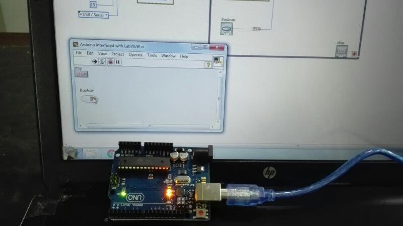
Tutorial 2: Programming Arduino with LabVIEW: In our last tutorial we have seen how to get started with LabVIEW. We answered what is LabVIEW? How its program looks like and How to make our first program in LabVIEW? Today’s tutorial is about the interfacing of LabVIEW and Arduino. We will explore about
- WhatArduino is?
- Why interfacing of Arduino is necessary with LabVIEW?
- Necessary softwares required for interfacing of LabVIEW and Arduino?
- How to make a program in LabView, upload it to Arduino and control it through user interface?
What Arduino is?
Arduino is open source hardware board with many open source libraries to interface it’s on board microcontroller with many other external components like LED , motors, LCD, keypad, Bluetooth module, GSM module and many other things one want to interface with Arduino board. Arduino is basically make from a microcontroller but Arduino have all external socket to connect with other devices and it also have built in programmer which is used to program Arduino from computer. So Arduino is a complete board which includes all things to connect with external peripheral and easy to program through computer. There are many Arduino borads are available. But in this article I will give you brief review of Arduino UNO R3 which is very popular board among engineering students.
Arduino is the one of the most excellent electronic platform of the 21 st century; it has accompanied the entire micro controller system into a small and handy device. It is an open source hardware and anyone can used it due to its friendly and easiness and can be used to create complex project by simple programming algorithms. It is not only to use design and develop but also can test the prototyped and hardware infinite times. The hardware consist of different microcontroller depending on the model that you are using with other electronic components which can be programmed using its own software the Arduino IDE to do almost any task starting from a simple LED glowing to building an Mars Rover and Drone Systems. The human friendly nature of the Arduino language makes it easier for everyone who wants to build different prototypes and hardware for its own interest as well as for some industrial purposes. Additionally, it possesses a simplified version of C++ which makes it easier to build programs at your own.
Arduino is intended for the people who want to play, run and build the complex hardware’s without knowing very much of the programming skills and algorithmic knowledge. It’s the best open source platform currently available in the market and has created another revolution and usage after its huge demand in the public. Since it is open source hardware; so most of the programs and softwares are available on the internet. The development cost of Arduino it extremely small as compared with the other tech giant’s microcontrollers.
Its software files include the basic programs for a beginner in its source code libraries. A user can use them to make its project versatile and can further edit the program for improving its capabilities and it also possess strong online helping community platforms.
Following are the main features of Arduino UNO which we will use in our tutorials:
- 14 digital IO (6 can be PWM outputs)
- 32KB program memory
- 6 Analog Inputs (10 bit resolution)
- Interfacing port
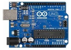
Fig. 1: Arduino UNO Board
Why interfacing of Arduino is necessary with LabVIEW?
Ardunio is open source hardware board and it is very easy to perform complicated tasks with it. It not only has many built in features but also supports external devices. But it requires writing different lines of code which could be cumbersome. Here comes in the LabVIEW to rescue you. LabView uses graphical language and do not require writing lines of code. Instead we use graphical diagram to perform particular task. You can have a look at tutorial 1 for more details.
Interfacing of LabVIEW and Arduino combines both the simplicity of Aduino hardware board and the graphical language of LabVIEW. Now we do not need to write lines of code and also we do not need the other complex hardware boards.
Necessary softwares required for interfacing of LabVIEW and Arduino?
Here is the list of software you are required to install for interfacing of Arduino and LabVIEW. All software are free and easily available.
-
(You might already have it if you installed LabVIEW. If not download.)
- LabVIEW Interface for Arduino(Present in Visual Package Manger. Download and install it)
After installation test your installation using sample program at the “finish” dialogue box.
How to make a program Arduino with LabVIEW
In our program we will control an LED on real time hardware using a Push Button in LabVIEW.
- Start the LabVIEW.
- Creat Blank VI as in Tutorial 1.
- Go to “Block Diagram” Panel
- Right Click on white space. Go to “Arduino” and select “init”.
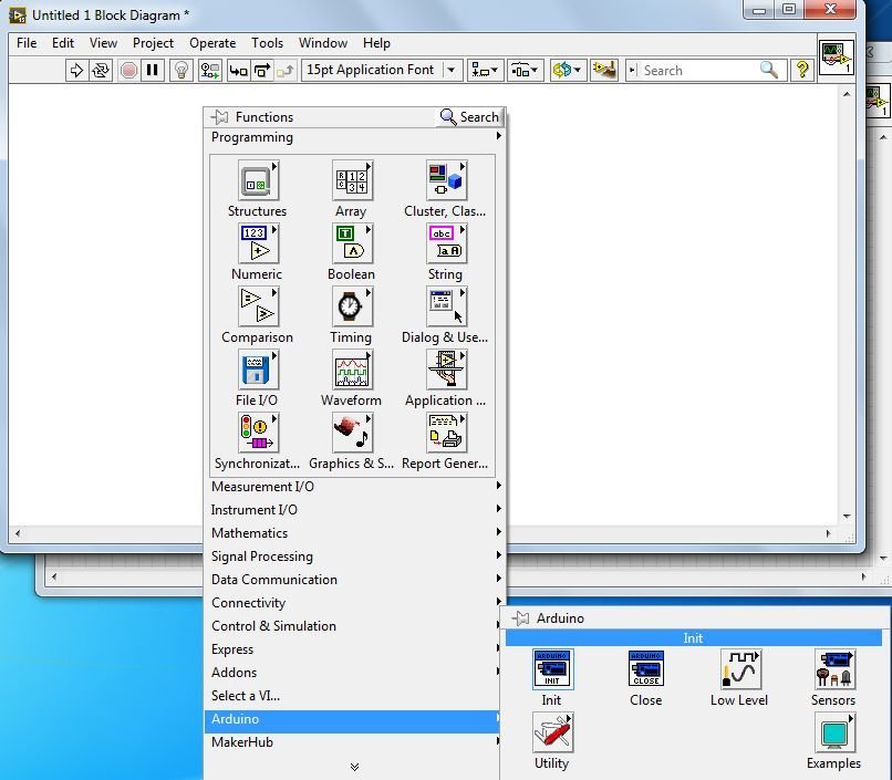
- Bring Cursor to anywhere in “Block Diagram” panel and place the “Init”.
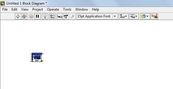
- First input is “VISA resource”. It is the serial port you are using for interfacing of Adruino. You can find it in “device manager” of your computer under “ports (COM & LPT)….” Make sure Arduino board is connected with computer otherwise it won’t be shown. In my case it is COM4.
- Bring cursor on first input of “Init” until it shows “VISA resource”. Right click on it. Go to “create” and select “constant”. As it will be a constant value of Port which will be always used for serial communication.
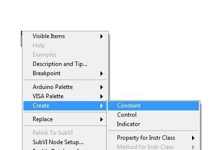
- Click on arrow it will show available option. In my case its “COM4”. Select appropriate one after checking from device manger as mentioned above otherwise it won’t work.

- Second input is “Baud Rate”. Create it as constant as done for “VISA resource”. Right click on “Baud Rate” then “create” and then “constant”.
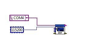
- Third input is “Board Type”, fourth is “Bytes per packet” and fifth is “Connection type” make them also constant.
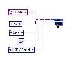
- Click on white space on “Block Diagram” and follow “Arduino → Low Level → and select Set Digital Pin”

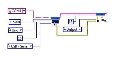
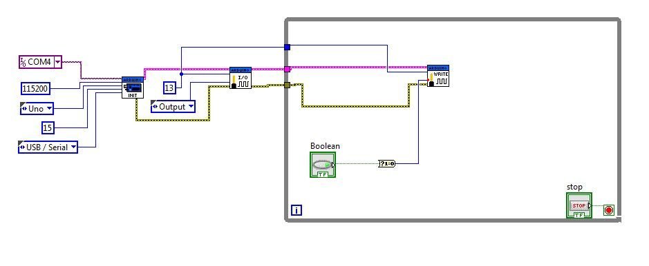
- Place “Set Digital Pin” on “Block Diagram” and join “Arduino resource” of both blocks. Create “digital I/O pin” as constant. And write 13 in it. It will be pin we will control. Make second input “Pin Mode” as constant and select output from drop down. It means pin will work as output pin. Join “error in” with “error out” of other block. If any error occurs in previous block, it will travel to next block. We will elaborate its purpose at end of article.
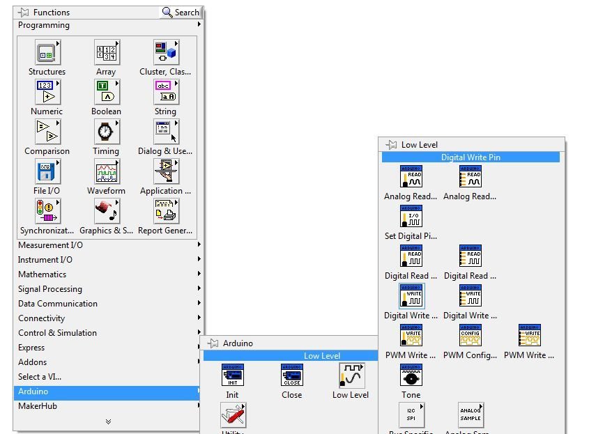
- This completes what we do in setup loop of Arduino program.
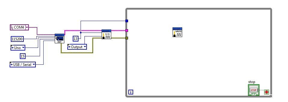
- Click on white space on “Block Diagram” and follow “Arduino → Low Level → and select Digital Write”. Place “Digital Writ ” on “Block Diagram”.
- Now next as we do in program; we place DigitalWrite function in void loop, we will do same here.
- Click on white space on “Block Diagram” and follow “Structure → select While loop”.

- Draw a rectangle on “Block Diagram” and click on red color round icon “loop condition”Create a constant by right clicking on it. I will show a “STOP” icon on diagram.

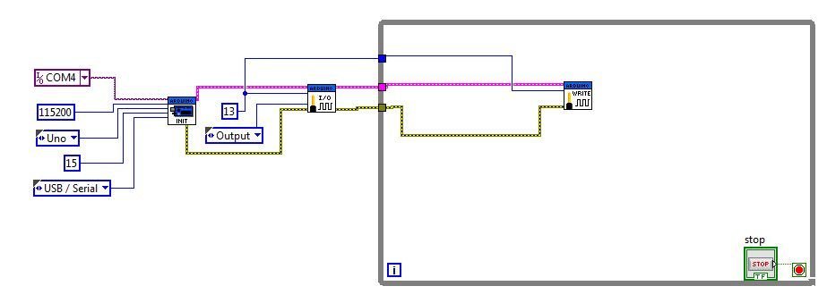
- Bring “Arduino Resources, Error Out and Pin 13” on rectangle.
- Connect “Resources with Resource”, “Error with Error” and “Digital IO with Pin13”.
- For creating “value” input go to Front Panel. Right click “silver → Boolean → Push Button” and Place it in Front Panel. It will also be shown in “Block Diagram” automatically.
- Bring the Boolean in while loop and find “Boolean to (0,1)” as follows.
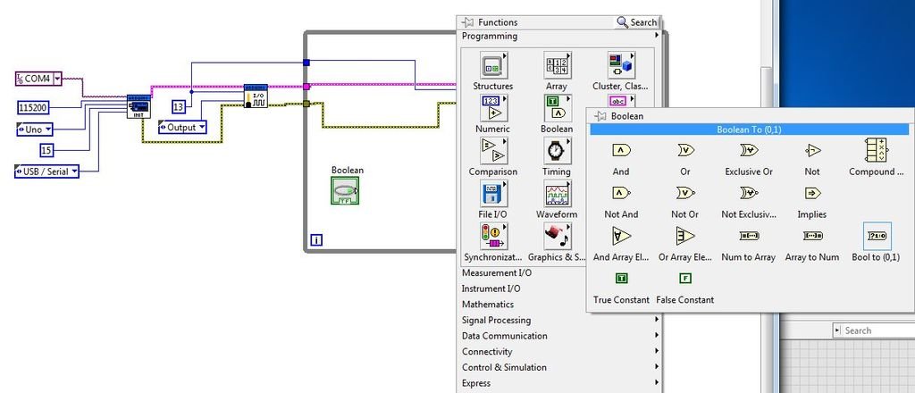
- Place “Boolean to (0, 1)” in “Block Diagram” and connect as shown.
- Find “Close Block” as Follows.
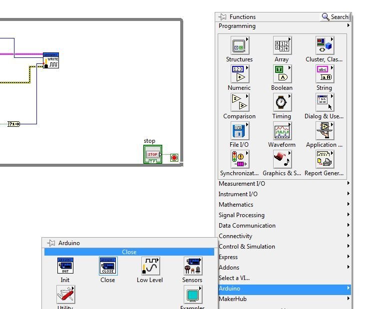
- Connect Close Block as Follows.

- Now Start Ardunio IDE.
- Click “File” then “Open” and Follow as shown. Go through all these folders from “Computer” onward and open LIFA_BASE Arduino file.
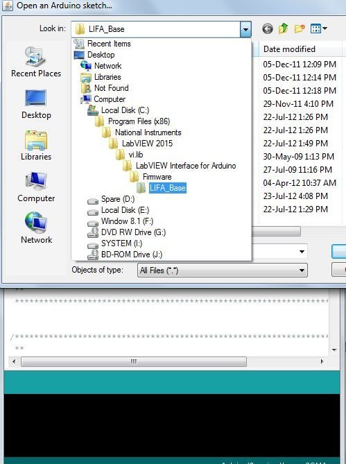
- Upload the program opened using Arrow button on top of Arduino IDE.
- Once uploading done close the Arduino IDE. It’s very important to close it because both LabVIEW and Arduino are using COM4. If not closed LabVIEW will not be able to communicate and it will crash.
- Now go to Front Panel in LabVIEW and run the program.
- Once both the Tx and Rx lights are ON; on Arduino board press Boolean button on Front Panel. You will observe LED on board connected with pin 13 is ON when we press push button on LabVIEW once. Pressing Again send 0 so LED will be OFF.
LabVIEW and Arduino: Get Started in Minutes.

A couple of weeks ago, as I was changing jobs, my (now) former employer asked me to give a crash course in LabVIEW. The audience consisted of interns who would possibly take over my LabVIEW work.
After thinking about it, I thought: “Let’s pull in some cheap hardware (An Arduino) and hook it up with LabVIEW… That should keep these young spirits engaged”. So I want to share that experience with anyone who is trying to do the same thing.
The Plan
So the first exercise was to have LabVIEW show an LED that would follow the Arduino’s On-Board LED:
- There is already a standard sketch to “blink” an LED for Arduino Devices. We only have to send the state of the LED over Serial Communication for LabVIEW to intercept and update accordingly.
- On LabVIEW side, there is already the standard “Serial Communication” example. It can be modified to incorporate a loop, a stop button and a LED that turns ON or OFF following the Arduino’s lead.
Time to completion: Less than 10 minutes.
Phase 1: Arduino
The Best Code is the Code not written…
So in the Arduino IDE:
- Select the “Blink” Example (File > Example > 01 Basics).
- Setup parameters (Board Type, Comport,…) in the IDE for your board (Any board that runs Arduino will do).
- Download the sketch on your device, and verify you have a LED that blinks.
If it does, we can move to the next step:
Update Blink LED Sketch
In the Setup section, we will initialize Serial Communication at 9600 Baud Rate. We will then publish a message just after the LED state changes.
Phase 2: LabVIEW
As stated previously, there is already an example shipping with all versions of LabVIEW. It does most of what we need.
Close the Arduino Serial Monitor before proceeding… since LabVIEW is going to try to open that Comport too.
- Navigate to LabVIEW Example (Help > Find Examples), and look for “Simple Serial.vi”
- Open this VI, setup Comport to match configuration in Arduino IDE (see above)
- Run the VI, and you should see the message published by the Arduino device.
If that worked then we can proceed to updating the VI.
Update “Simple Serial.vi”
See all updates made to the “Simple Serial.vi” in blue below.
- We clear the I/O Rx Buffer every time our application starts, since the device pushes messages even when no one is listening. This buffer will fill up and create a backlog for LabVIEW that needs to be fully processed before its LED state (named “Remote LED State”) follows in Real Time the state of the Arduino LED.
- We add a while loop and stop button and make sure to exit the loop on error. Also, close the VISA session references outside the loop.
- We parse the message received from the Arduino. If it contains “ON” we switch on the LabVIEW LED.
- We handle a corner case: Since we read from the serial port faster than the device publishes messages, what do we do with our LabVIEW LED when we haven’t received anything? One Simple solution is to remember the previous valid value (using the shift register) and use that instead.
Okay, that’s the gist of it. The idea is that someone who is just getting his feet wet using these two technologies can find some (hopefully) helpful resource here to get him started.
Bonus
The scenario above has the Arduino device controlling the LED and LabVIEW acting as an indicator for its state. Let’s turn things around and let LabVIEW control the LED now.
Arduino Sketch
Once again, we will update an Example shipping with the Arduino Installation (File > Examples > Communications > ReadASCIIString).
LabVIEW VI
We will update the previous VI to include sending command to the Arduino. See comment in Green.
And that’s it! Now, changing the state of the control button in LabVIEW forces a change of state on the Arduino device which then publishes its new state on the comport. LabVIEW then updates its own LED to follow the content of the message published. Easy Peasy,…
As I said, previously, I had to put together this small tutorial as a means to get new interns to started with LabVIEW. I’m documenting it here for public use.
That’s it for me. If you have questions / comments / remarks, get in touch.