
Miner status page explained
The miner status page in this article applies to all Antminer.
When you log in to your miner on the Internet and open the miner status page, you will see many unfamiliar abbreviations and numbers.
This article will explain these abbreviations and numbers so that you can better understand what the Miner Status page tells you.
The page is divided into 3 parts:
In the “Summary” section:
 Elapsed:
How long has the miner been running for?
The screenshot above tells us that this miner has been running for 17 days, 16 hours, 8 minutes and 51 seconds. It takes about 20 minutes for a miner to run stably.
GH/S(RT):
The real-time hash rate of your miner. The letter "G" is a number prefix, which is 109 in the case.
GH/S(avg):
The average hash rate of your miner in the elapsed time.
Please note that different miner models have different hash rates, so the prefixes are different.
Foundblocks:
The number of blocks that miner helped the mining pool solve.
Please note that the numbers do not mean that you will be paid in full, as this is a mining pool mining. The payment will be based on the amount of work your miner has done to resolve this block (if reported).
Localwork:
Work that is available to your miner from the mining pool.
Utility:
The number of shares/contributions your miner submits per minute.
WU:
BestShare:
Shows the difficulty value corresponding to the lowest hash value launched by your miner so far. The difficulty will determine the highest hash value that can be solved for the block.
If the hash value calculated by your miner or mining pool is lower than the maximum value, then you or the mining pool has already solved a block.
(After a period of time, your miner submits the most difficult share).
In the “Pools” section:
 URL:
URL:
Your mining pool server addresses.
User:
Your miner pool’s worker name.
Status:
Pool status. "Alive" means the miner can connect to the server. "Dead" means the miner cannot connect to the server. As long as one of the three states is "Alive", no action is required.
Diff:
Accepted shares:
Work submitted by your worker that was accepted by the pool.
Discarded:
Shares that were never submitted to the pool.
This could happen because someone solved that share first, or maybe the block was solved and the miner restarted the work.
Stale:
Work that your miner submitted for a block that was already solved.
LSDiff:
Last Share Difficulty and LSTime is the time since the last share.
DiffA#:
Difficulty of the last "A"ccepted share.
DiffR#:
Difficulty of the last "R"ejected share.
DiffS#:
Difficulty of the last "S"tale share.
In the “Antminer” section:
 Chain#:
Chain# of the control board connected to a hash board.
(Zoom in to see the chain# clearer)
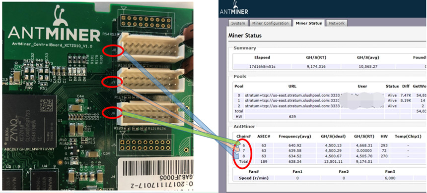
ASIC#:
The number of working chips on a hash board connected.
Frequency:
Hash board frequency.
GH/s (ideal):
Ideal or expected hash rate. The letter "G" is a number prefix, which is 109 in this case.
GH/s (RT):
Real-time hash rate.
Note that different miner model has a different hash rate and hence the prefix is different.
HW:
HW errors or faults.
Hardware errors are normal and expected in a good working miner. Hardware errors occur because the chips are working at full capacity. The miner usually corrects the problem and continues hashing as normal.
If the miner is hashing well then it is correcting the errors and no action is needed.
Temp chip:
ASIC chip's temperature.
Temp PCB:
Check your miner's normal operating temperature here>
ASIC status:
Normal status: “0” means normal, you should find 63 (or the number of chips in your specific miner) “0”s in this field.
Abnormal status: ”X” means that a certain chip is not working. If ASIC# number is 100 and in the ASIC status the number of ”0”s is less than 100, it means some chips are missing or cannot be detected.
High Temperature PCB
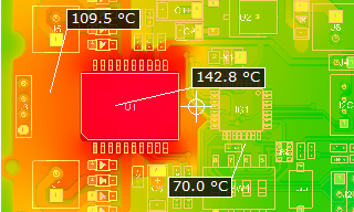
Modern Printed Circuit Board(PCB) designers are creating PCBs geared towards increasingly high performance, and as a result, power densities are exponentially increasing. With the increase of power usage in the PCB, the heat generated in the PCBs also increases. This brings out the necessity of dealing with heat in PCBs. Also, specific applications require PCBs to operate under high temperature environments to manage and transmit high amounts of heat.
Traditional PCBs have a lower tolerance for heat. Reaching the maximum level may add impact their performance. And, prolonged exposure to heat will cause irreparable damage. The longevity of the electronics in which PCBs and their components are incorporated depends on how well thermal loads are managed. This is an important factor that subjects manufacturers' attention when designing PCBs used in autos, LED lighting, and alternative forms of energy. In these scenarios, the embedded PCBs tend to get open to high-temperature levels, higher than a laptop computer's circuit board.
What are High-Temperature PCBs?
High-Temperature PCBs are printed circuit boards made from materials with a Glass Transition Temperature higher than 170 °C. Glass Transition Temperature(Tg) is the temperature above which the material is turned from a hard and relatively brittle 'glassy' state into a viscous or rubbery form. As a good rule of thumb, PCBs should be designed for continuous thermal load at temperatures 25 degrees below Tg. In case your PCB will be operating at 130 degrees Celsius or higher, it is recommended to use a material that is considered a high Tg material.
High Tg Materials are:
- Good at resisting high temperatures
- Have low thermal expansion
- Have a more extended delamination durability
In PCB manufacturing which refers to a glass-reinforced epoxy laminate material, manufacturers use FR4 as the most common material. It contains woven fibreglass along with a flame-resistant binder composed of epoxy resin. Standard FR4 Tg lies between 130- 140 degrees Celsius, and High Tg FR4 is available for high-temperature PCB applications. Not only do high Tg FR4 boards handle higher temperatures, but they also have higher moisture resistance.
When power components or other heating devices are in the design, using PCBs with metal cores is one of the most popular techniques to avoid overheating. Insulated metal core PCBs, commonly known as MCPCBs or IMPCBs, are also possible. Using of larger surface area in the metal layer makes it easier for the heat to escape. When you use a metal PCB core, pay attention to vias to drilled below power or other heat-generating components.
Employing a thicker metal core with vias will disperse more heat than without using these two techniques side by side since vias enable the use of thicker metal cores. As we mentioned earlier, an insulated metal core is a PCB core design option. Here, a thin glass or resin layer insulates the core. The insulating mounting's design will keep heat energy from redistributing into the electrical components on the PCB and instead directing it through the core to the atmosphere. IMPCB frequently engages in applications where the power components are present.
From what we have discussed so far, it must be clear that Material selection is a vital part of designing PCBs that can withstand high temperatures. However, materials by themselves will not be enough to offset the bad design choices you’ve made along the way. Heat management must also be a key consideration when designing a PCB.
Methods of Temperature Management in PCBs
There are three main ways to heat loss in PCBs. They are Radiation, Convection, and Conduction. The design team must consider all three when regulating system and component temperatures.
Heat Radiation
Phenomenon Radiation is referring to the emission of energy from electromagnetic waves. We often only associate it with glowing objects. Although in reality, any object with a temperature higher than absolute zero emits thermal energy. Electromagnetic waves must travel a somewhat direct path from the source to remove heat effectively. Reflective surfaces prevent photons from leaving, forcing many of
them to return to their source. In a worst-case scenario, reflecting surfaces could combine to create a parabolic-mirror effect. This would concentrate the radiated energies from several sources and focus them on one hotspot of the system. So it will lead to resulting in serious problems. The temperature of the source (in absolute values, raised to the fourth power), the material's thermal emissivity, and the radiation-emitting surface area are the main determinants of thermal radiation.
Heat Convection
Under the phenomenon of Convection, the heat will transfer via fluids such as air, water, or another substance. A certain amount of convection occurs «naturally». The fluid absorbs heat from a source, loses density, rises to a heat sink, cools, gains density, sinks back to the source, and repeats the cycle. Using a fan or a pump may speed up the convection. The temperature difference between the source and coolant, the ease with which the source transfers heat, the ease with which the coolant absorbs heat, the flow rate of the coolant, and the surface area over which the heat is transported are the main variables impacting convection. Liquids significantly more easily absorb heat than gases.
Heat Conduction
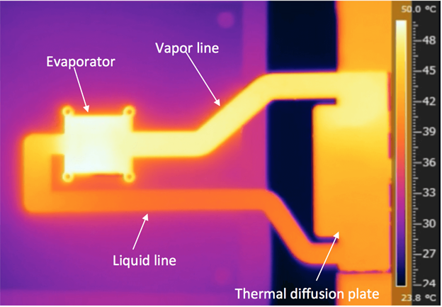
Conduction is the direct transport of heat from the heat source to the heat sink. The amount of heat transported per unit of time is the temperature difference between the source and sink. Moreover, the ease with which heat flows through a thermal conductor is related to various aspects. They are electrical current, including voltage, amperage, and conductance.
Since both represent molecular or atomic motion types, the characteristics that make an excellent electrical conductor also tend to create good thermal conductors. For instance, copper and aluminium are both tremendous conductors of heat and electricity. Large conductor cross-sectional areas increase heat conductivity and electron conductivity. Additionally, a path's length can degrade the conductor's effectiveness.
Minimize the Effect of Heat Conduction
The primary method used to remove heat from a circuit board is typically to route it to a suitable heat sink. For that, it should be concerned, where convection disperses it into the surrounding air. While some heat is radiated and wafted straight from the source, the majority is often taken away through pathways known as «heat vias» or «thermal vias.» PCB heat sinks are relatively large, highly emissive surfaces bonded to conductive (like copper or aluminium) backings via a labour-intensive process. Frequently corrugating or finning are steps for maximizing the surface area. The machine's chassis may also be connected to PCB heat sinks to utilize its surface areas. Fans often provide the flow of cooling air. In severe circumstances, the air has the ability to act as the cooler in a gas-liquid heat exchanger.
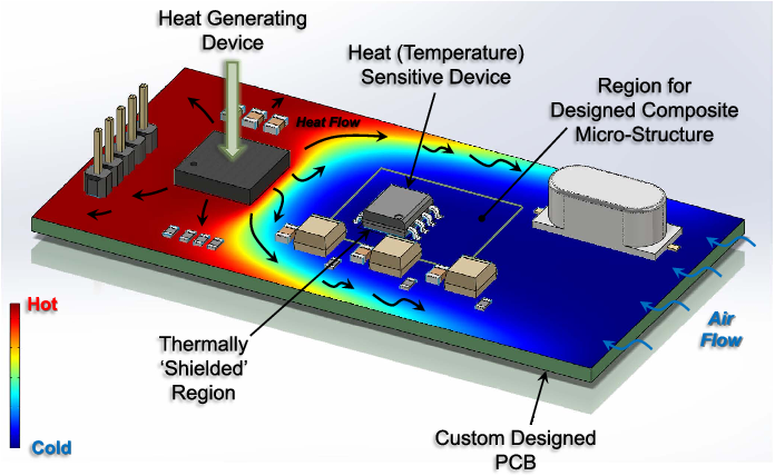
When it comes down to it, a designer's options for managing heat include decreasing power densities, removing or isolating the device from heat sources, including larger fans and liquid cooling systems, increasing the size and accessibility of heat sinks, using more prominent conductors, and using exotic materials that can withstand higher temperatures. They are the main concerns at the outset of idea development and design since they have an impact on the cost, volume, and weight of the complete system.
Modern High-Temperature Management Techniques
Standard fabrication techniques have limitations, and PCB producers are well aware of this. They work to stay current with design issues by introducing new PCB types specifically made for high temperatures. While these PCBs use heavy copper circuits to increase their current-carrying capacity. Furthermore, to reduce I2R losses, their specifics can differ significantly.
We see more and more «heavy copper» and «extreme copper» boards, which, as the names suggest, use heavier, thicker copper layers than typical PCBs. If heavy (or extreme) copper is not necessary everywhere, ordinary and heavy copper circuits can couple to transport power and signal currents on a single board.
Heavy/extreme copper PCB fabrication is comparable to conventional PCB fabrication, except for unique etching and plating procedures. The benefits include increased mechanical strength, lower I2R losses, lower I2R losses, higher current carrying capacities, and the opportunity to add features like on-board planar transformers and high-efficiency on-board heat sinks (owing to the ability to combine heavy and standard circuits on a single board). As usually in bonded heat sinks, manually fabricating is not an essential factor for the onboard heat sinks. Therefore this is a low-price technique.
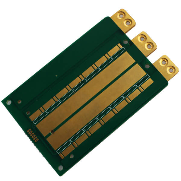
Instead of using heavy/extreme copper plating, a different strategy is to implant heavy rectangular copper wires. The benefits compared to standard PCBs are comparable to those of heavy/extreme copper PCBs and include the ability to combine power and signal currents, improved heat dissipation, increased strength, removal of connectors, fewer layers, and a smaller total system volume. Some assert that soldering a wire-embedded board is simpler than a thick copper board. However, you have to determine this case by case.
Using Specialized Software
CFD Software
Computational fluid dynamics (CFD) software connected with standard PCB design packages, such as Mentor Graphics' FloTherm PCB®. Old rules-of-thumb and back-of-the-napkin heat computations lose accuracy as performance boundaries get change according to the push exerted by modern designers. When appropriately used, decent CFD software, particularly one created expressly for PCB or electronic cooling applications, can reduce time to market, enhance design efficiency, alleviate potentially expensive errors, and eliminate a lot of guesswork.
PDN Analyzers
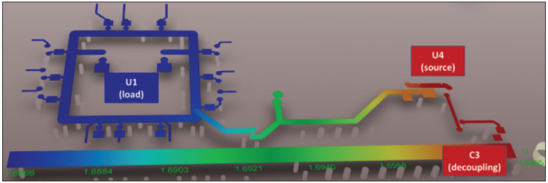
Power Delivery Network(PDN) Analyzers can simulate current flow through any nets you identify as being in the critical path, either simultaneously or sequentially. Ensuring the dependability and safety of your product, the peak current densities and excessive current vias get subject to quick discovering and highlighting. The voltage from a power source will deliver to downstream voltage regulator modules by your circuit board's PDN. There are modules that help with power regulation and distribution to the next component. But, how much power and the amount of voltage are wasted through your board depends on the layout of your PCB. You can obtain a current density map of your PCB to identify potential hotspots. So in the case of high-temperature PCBs, whether they comply with the IPC 2152 standards to ensure that excessive temperature elevations have not resulted.
A Final Word
Their thermal loads directly impact PCB performance and longevity. Due to this, managing heat dissipation, or the lack thereof, is crucial for designing and producing PCBs. Everything must be considered, including the heat produced by the PCB's components, the environment around it, and its intended function. Researchers are still working on research studies related to components and circuits that can disperse heat and moisture more effectively. Designers must limit heat loss and utilize extra removal methods when natural cooling is insufficient to avoid thermal issues. It's important to consider component requirements, PCB layout, PCB dielectric material, and environmental factors while creating a thermally efficient design.
Temp pcb что это

PCB temperature is an important indicator of safety, reliability and performance. Excessive temperatures are likely to cause failures and permanent damage.
During the PCB manufacturing process, there are several conditions that can generate more heat. For example, external component mounting, drilling and soldering processes, inadequate environmental ventilation and other factors can generate excessive heat, which can lead to damage to the board.
In either case, effective PCB cooling techniques and PCB thermal management can significantly control excessive PCB temperatures. In this article we will explain in detail there are issues related to PCB temperature.
How to measure the PCB temperature?
Before measuring the PCB temperature, you first need to determine the main heat source in the PCB, usually a microcontroller or processor, or locate the temperature sensor.
Next, find the connection to the ground (GND) pins of the heat source substrate. most of the heat generated in the PCB is transmitted to the temperature sensor through these pins.
Then we can start measuring the PCB temperature, which usually involves the following three steps.
- Place a grounding layer between the temperature sensor and the heat source
- Connect the GND pin of each temperature sensing to the ground layer of the heat source
- Ensure that the temperature sensor and the heat source on the PCB remain close to each other
Common causes of high PCB temperatures
How much heat a PCB can withstand depends on the materials used to make it up. Materials with the best thermal properties can effectively resist the effects of temperature. In the selection of materials for PCB, you can choose a high TG material.
Some common causes of high PCB temperatures are.
- Component failure.
- Through-hole interference.
- Surface mount component distance.
- High frequency circuits. 5.
- Lead-free solder.
Why is it important to measure PCB temperature?
It is important to monitor the PCB temperature, too high a temperature can led to structural changes in the performance of the PCB, or even damage.
Overheating in the PCB can lead to damage to the following.
– Different material expansion rates
How to prevent excessive PCB temperature?
To prevent the PCB from heating up, engineers can take the following PCB cooling techniques.
Use heat sink
Heat sink can effectively and safely dissipate heat.
Use a cooling fan
Cooling fan allows the temperature to dissipate while allowing cold air to enter, helping to prevent the PCB from overheating.
Select heat-resistant materials
Compared to standard PCBs, thick copper PCBs have excellent resistance to high temperatures and can handle higher levels of current and provide stronger connection points.
Increase the board thickness and width
In PCBs, thicker boards tend to be less efficient than thinner boards in terms of thermal conductivity, which means that more power is required to enable thicker boards to reach high temperatures, which can effectively avoid PCB overheating.
Application laminate
High-temperature PCB laminates can prevent overheating by providing thermal protection for PCB components.
Use similar coefficient of thermal expansion materials
The coefficient of thermal expansion (CTE) measures how much a material expands when exposed to high temperatures. In a PCB design, the ideal dielectric layer has a similar CTE to the copper layer. this way, if the layers expand, they will expand in a uniform manner, thus minimizing damage.
Maintain adequate spacing
When circuit board components are too close together, it may lead to crosstalk and increased alignment resistance, resulting in resistance loss and increased circuit heat.
Integrate heat pipes
The liquid in the PCB heat pipe piping absorbs heat and prevents it from damaging the board components.
Contact KingPCB
When you are looking for a PCB that can be specifically designed for temperature control, KingPCB is your trusted partner with extensive manufacturing and assembly experience to help you evaluate your project, and a professional team to help you manufacture your PCB efficiently.
Temp pcb что это

Glossary and Directions for the Miner Status Page of Antminer Series
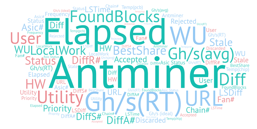
In this article, we will explain the Miner Status page of Antminers. For setting rigs up, please refer to our tutorial: www.eastshoremining.com/tour/
We will take Antminer S9 as an example. In the Miner Status tab, there are 3 sections of info: Summary, Pools and Antminer.
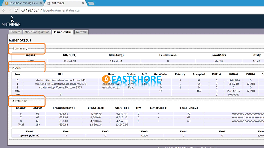
The “Summary” Section
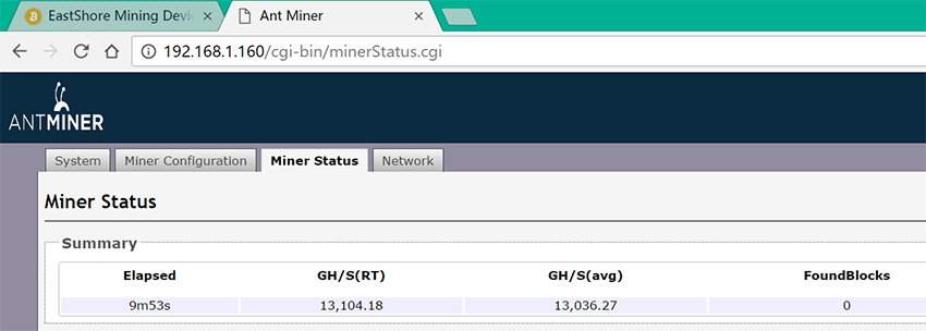
Elapsed: this indicates how long the miner has been working
GH/S(RT): real time hash speed
GH/S(avg): average hash speed
FoundBlocks: number of the blocks that the miner has helped the pool to solve. Note that the numbers don’t mean you are getting the full block payment because it’s a pool mining. Payout will be based on how much work your miner has contributed to solving this block.
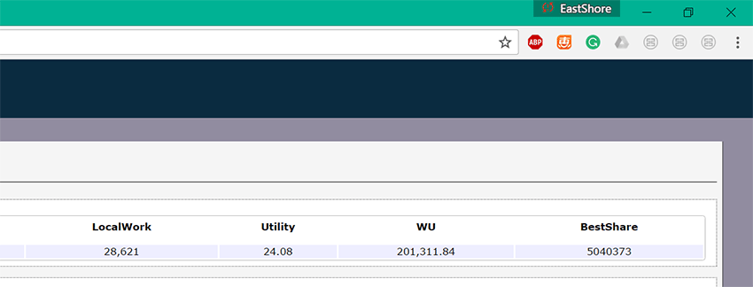
LocalWork: this indicates the work the miner is solving.
Utility: utility is the measure of how many shares are submitted per minute.
WU: WU means “Work Utility”. Work utility is the product of hashrate * luck and only stabilizes over a very long period of time. Assuming all your work is valid work, bitcoin mining should produce a work utility of approximately 1 per 71.6MH. This means at 5GH you should have a WU of 5000 / 71.6 or
69. You cannot make your machine do “better WU” than this – it is luck related. However you can make it much worse if your machine produces a lot of hardware errors producing invalid work.
BestShare: if your miner or pool computes a hash value that is lower than that maximum, then you or the pool have solved a block.
The “Pools” Section

URL: this is the pool address
User: the user name of the worker
Status: status of pool connection. Alive means it is connected to the pool. If otherwise, it will show “dead”.
Diff: mining difficulty.
Priority: the priority of the pool you set. Usually, the miner will try to connect the pool with the priority “0” first, if failed, then it will try to connect the pool with the priority “1”, then the priority “2”, and so on.

Accepted: this indicates the shares accepted by the pool. Any shares that were “accepted” by the pool are set in stone (unless you delete your worker or your account).
DiffA#: the difficulty of the last Accepted share.
DiffR#: the difficulty of the last Rejected share.
DiffS#: the difficulty of the last Stale share.
Rejected: If your miner successfully performs work, but submits it too late for that block, it is called a ‘rejected share’ of work. You will get no credit for that work, and it cannot be banked towards future coin generation. Rejected shares are inevitable, regardless of how powerful your mining computer is. The desired goal is to minimize rejected shares and maximize accepted shares.
Discarded: this indicates the shares that were never turned into the pool. Maybe someone solved that share first, or maybe the block was solved and the miner restarted the work. Discards are not rejects, they aren’t even shares. It means your miner had work prepared to hash but instead it discarded it in favor of newer/fresher work. You aren’t wasting any hashes when your miner discards work.
Stale: stale is when your miner submits work for a block that was already solved. This means your miner wasn’t notified about the new block yet, it’s inevitable.
LSDiff: last share difficulty.
LStime: time since the last share.
The “Antminer” Section
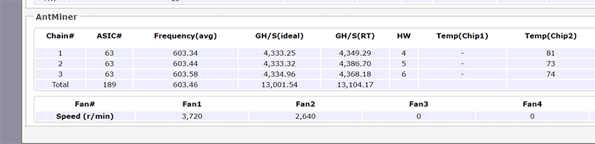
Chain#: hash board number. There are usually 3 hash boards in 1 Antminer.
ASIC#: the quantity of chips on each hash board.
Frequency: hash board working frequency.
GH/s (ideal): Ideal or expected hash speed.
GH/S(RT): the real time hash speed of the hash board
HW: hardware error.
Temp(PCB): temperature of the hash board
Temp(Chip): temperature of chips
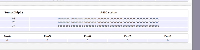
ASIC Status: status of the chips. 0 stands for normal, x stands for otherwise.
Fan#: speed of the fans
On the top of the page, there are other tabs (System, Miner Configuration, and Network) besides the “Miner Status” page, in which terms are easier to understand. We will explain the terms in those tabs if requested.