Arduino и OLED дисплей
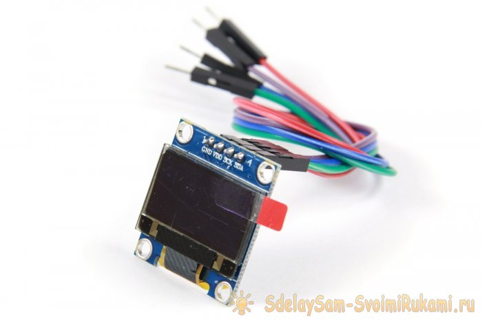
Набор GyverKIT комплектуется графическим OLED дисплеем:
- Разрешение: 128×64 пикселя
- Диагональ: 0.96″
- Контроллер: SSD1306
- Подключение: I2C
Подключение
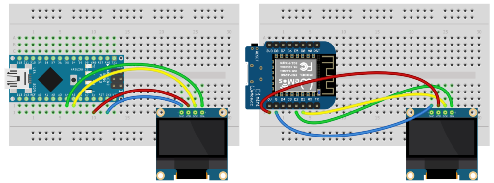
Модуль подключается на шину I2C и питание, как и любой другой модуль такого типа:
- Arduino: SDA – A4, SCL – A5
- Wemos: SDA – D2, SCL – D1
Библиотеки
Для данного дисплея существует несколько библиотек:
-
– мощная, но очень тяжёлая библиотека от olikraus – библиотека от adafruit – наша библиотека. Очень лёгкая и быстрая, поддерживает русский шрифт
В примерах на этом сайте мы будем использовать GyverOLED. Библиотека идёт в архиве к набору GyverKIT, а свежую версию всегда можно установить/обновить из встроенного менеджера библиотек Arduino по названию GyverOLED . Краткая документация находится по ссылке выше, базовые примеры есть в самой библиотеке.
Примеры
Библиотека имеет два режима работы: с буфером и без буфера:
- С буфером: занимает больше оперативной памяти, но позволяет выводить новые данные с наложением на старые. Требует вызова update() для применения изменений. Инициализация: GyverOLED<SSD1306_128x32, OLED_BUFFER> oled;
- Без буфера: на дисплей сразу выводится указанная графика, заменяя текущее отображение. Инициализация: GyverOLED<SSD1306_128x32, OLED_NO_BUFFER> oled;
Библиотека умеет делать print() любых типов данных и текста. Позицию вывода можно установить двумя способами:
L1: OLED Displays
Video. Playing Pong on the Adafruit monochrome 1.3” 128×64 pixel OLED display with the Parallax 2-axis joystick and tactile buttons. The source code for Pong is here. Parts of this video are sped up 4x.
In this lesson, you will learn about organic light-emitting diode (OLED) displays, basic graphics programming, and a brief introduction to two serial communication protocols called I 2 C (Inter-Integrated Circuit) and SPI (Serial Peripheral Interface)
OLED displays
Organic light-emitting diode (OLED) displays are relatively new technology, increasingly used in TVs, computer monitors, smartphones, and handheld game consoles. Unlike LCDs, which require backlighting, each OLED pixel generates its own light providing superior contrast and color control.
In this lesson, we will be using the monochrome (black-and-white) OLED displays from Adafruit along with their display control and graphics libraries. To do so, we need to install some libraries.
Install Arduino libraries
To use the Adafruit OLED display, we need two libraries:
- The Adafruit_SSD1306 display driver library, which handles display communication, memory mapping, and low-level drawing routines
- The Adafruit_GFX graphics library, which provides core graphics routines for all Adafruit displays like drawing points, lines, circles.
Fortunately, the Arduino IDE makes library installation easy. We can do it right from the IDE itself. Follow our step-by-step installation guide here.
Wiring the Adafruit OLED display
Once you’ve installed the requisite libraries, you’re ready to wire up the display!
The SSD1306 driver chip and accompanying library provides two different communication methods—each require different wirings: I 2 C (Inter-Integrated Circuit) and SPI (Serial Peripheral Interface). The default is I2C, which is what we will use in this lesson. For more on the SPI mode, see Adafruit’s official docs.
While the OLED display requires a 3.3V power supply and 3.3V logic levels for communication, the Adafruit breakout board includes a 3.3V regulator and level shifting on all pins, so you can interface with either 3V or 5V devices. Additionally, recall that the I 2 C requires pull-up resistors on the clock (SCL) and data (SDA) lines so that both are pulled-up to logic level HIGH by default. Thankfully, the Adafruit breakout board also includes these resistors. So, the wiring is quite straightforward, consisting of only four wires!
The wiring diagram and circuit schematic are below. We used the Qwiic color-coding system for our wires: blue for data (SDA), yellow for clock (SCL), black for ground (GND), and red for the voltage supply (5V). The I 2 C pins differ depending on your board. For example, on the Arduino Uno, they are A4 (SDA) and A5 (SCL) rather than digital pins 2 (SDA) and 3 (SCL) as they are on the Leonardo.
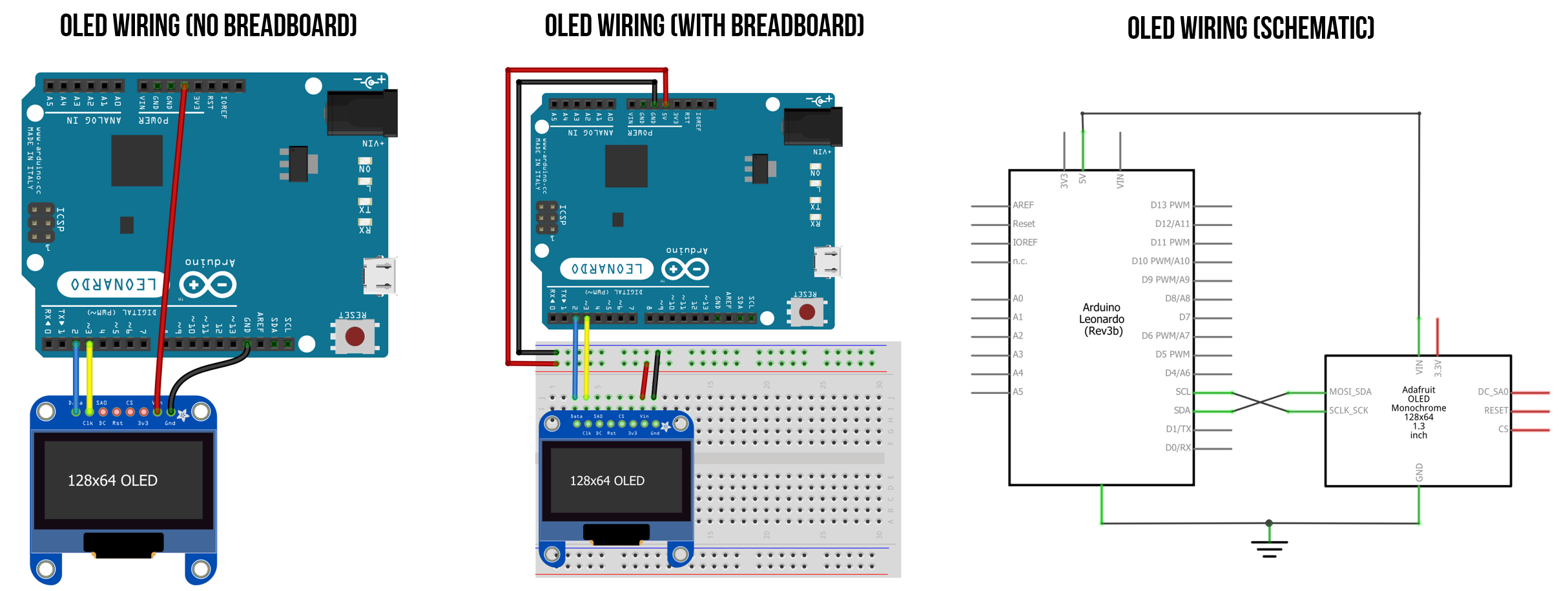 Figure Wiring the Adafruit OLED display requires only four wires (and nothing else). I used the standard STEMMA QT color coding for my wires: blue for data (SDA), yellow for clock (SCL), black for ground (GND), and red for the voltage supply (5V). Note that the I 2 C pins differ depending on your board. For example, on the Arduino Uno, they are A4 (SDA) and A5 (SCL) rather than digital pins 2 (SDA) and 3 (SCL) as they are for the Leonardo.
Physical wiring with jumper cables
Here’s a picture of actually wiring up the OLED using jumper cables.
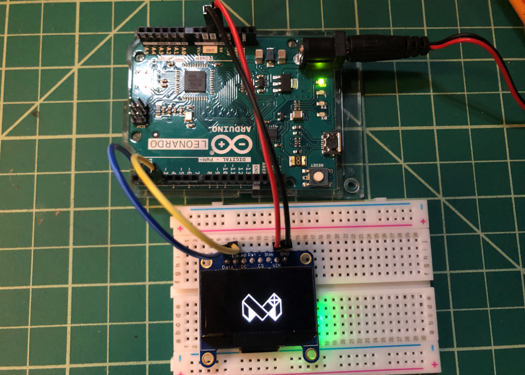 Figure Physically wiring the OLED display with jumper cables. The Arduino is running this demo code ‘BitmapBounce.ino’
ESP32 wiring
Some students have asked for the ESP32 wiring, so here it is. The ESP32 board runs at 3.3V vs. the 5V supplied by the Arduino Leonardo and Uno; however, the OLED itself only needs 3V for operation. You can learn more about the ESP32 here.
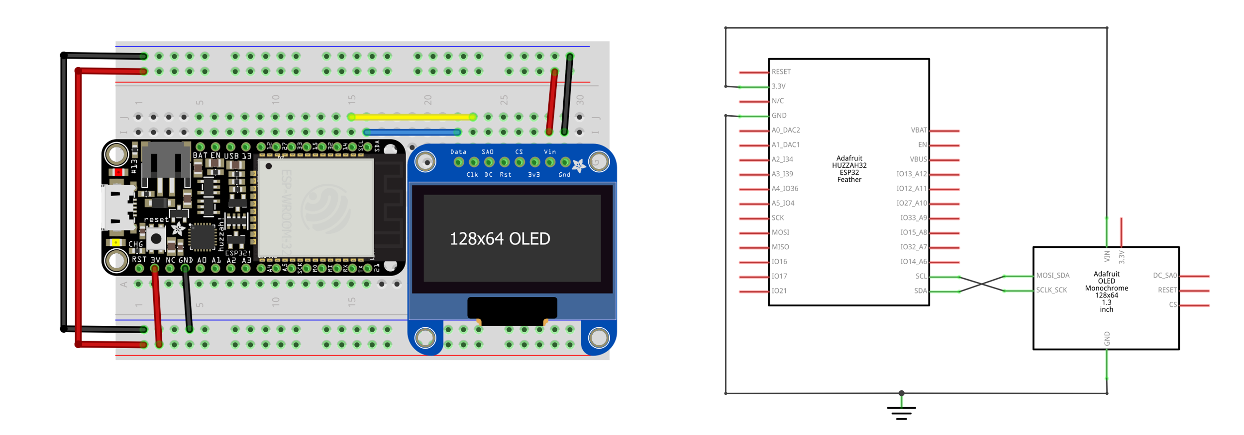 Figure. Wiring diagram for the Adafruit Huzzah32 ESP32 board with OLED.
STEMMA QT wiring
2017, many Adafruit and SparkFun breakout boards began including standardized connectors to more easily connect multiple electronic devices without soldering or working with lots of individual wires. This is particularly helpful because I 2 C let’s us daisy chain I 2 C-compatible devices together. The Sparkfun connection standard for I 2 C devices, called Qwicc, was later adopted by Adafruit, which they call STEMMA QT.
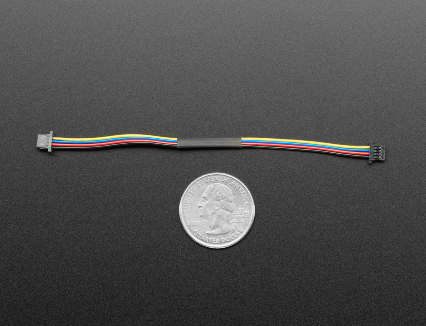
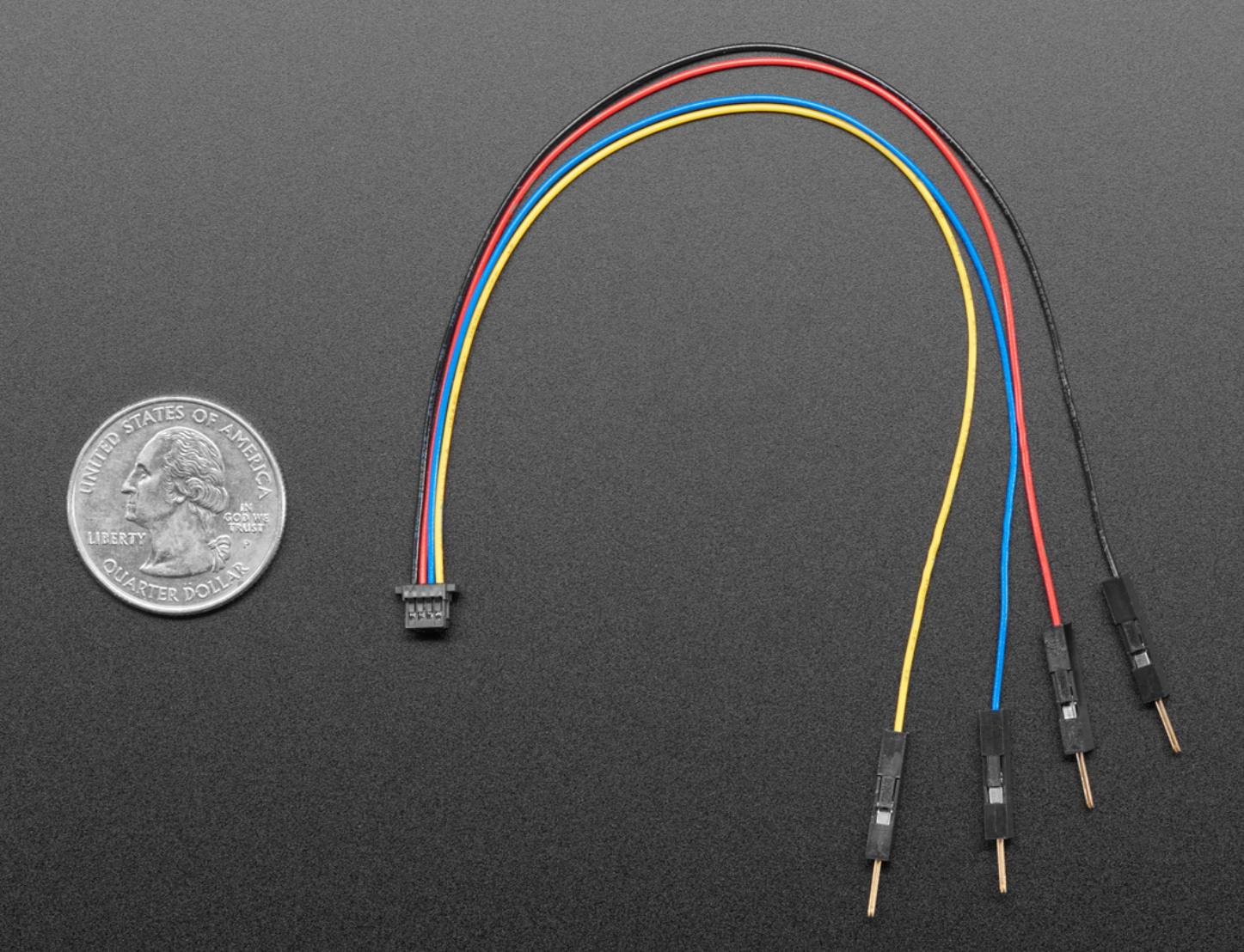
Both Sparkfun and Adafruit sell a variety of Qwiic/STEMMA QT cables, including this female-to-female version (for
$0.95) and this female-to-male jumper cable version ($0.95). You can use the female-to-female cable to daisy chain multiple devices together.
| STEMMA QT / Qwiic Female-to-Female Cable | STEMMA QT / Qwiic Female-to-Male Jumper Cable |
|---|---|
 |
 |
The video below shows the OLED display hooked up to a STEMMA QT female-to-male jumper cable:
Video Running the demo ssd1306_128x64_i2c with a STEMMA QT cable.
Testing the OLED display
Once you’ve wired the OLED display, we’re ready to test it with some code!
We will run one of the examples that ships with the Adafruit_SSD1306 library called ssd1306_128x64_i2c . This example iterates through a variety of drawing demonstrations, including: drawing lines, outlining and filling rectangles, circles, rounded rectangles, and triangles, rendering text with different styles, and drawing and animating bitmaps. You can view the example source code here.
To open and run the example, follow these steps.
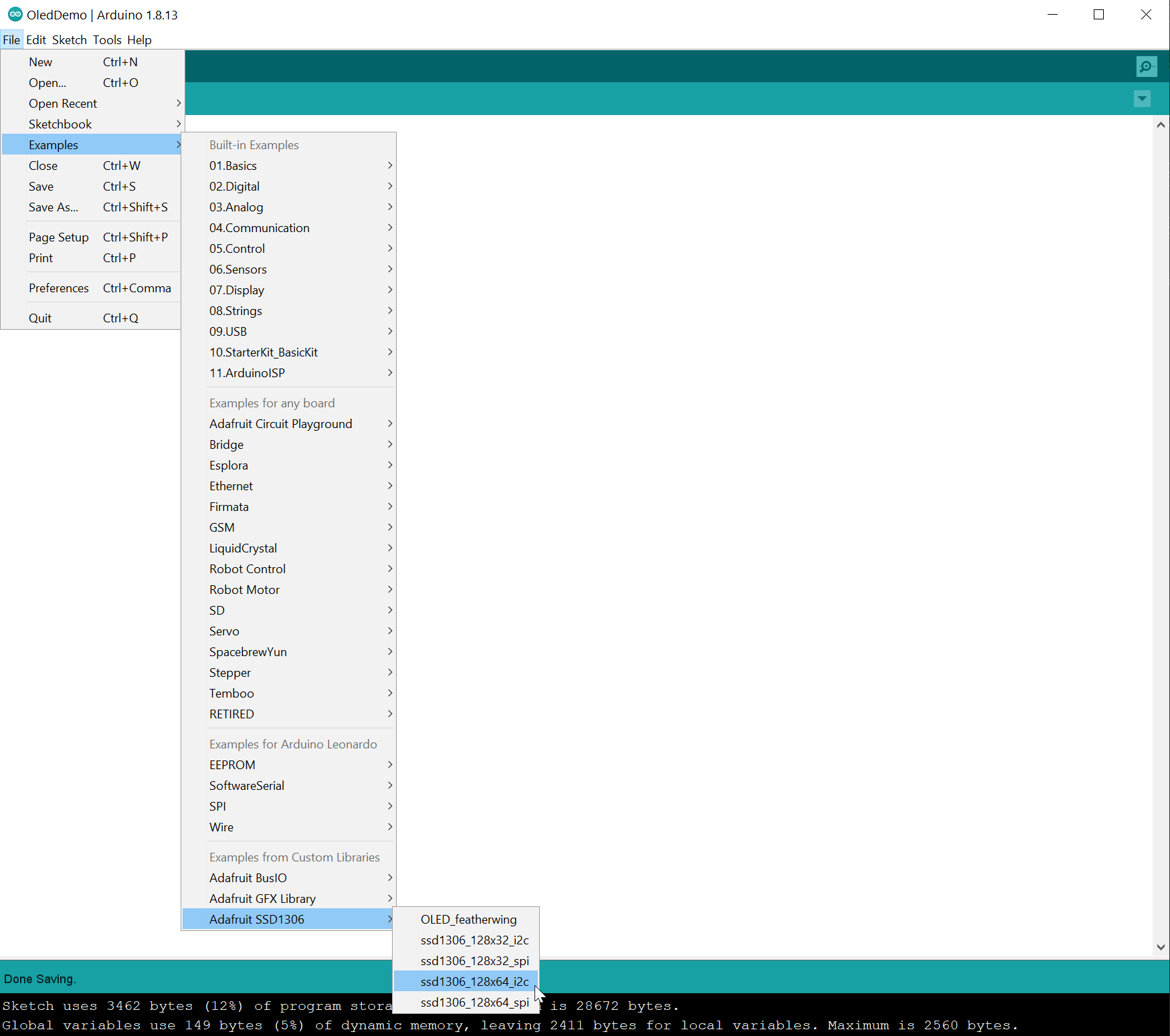
Step 1: Open the example
In the Arduino IDE, go to File -> Examples -> Adafruit SSD1306 and select ssd1306_128x64_i2c . You might have to scroll down in the Examples file menu to see it.
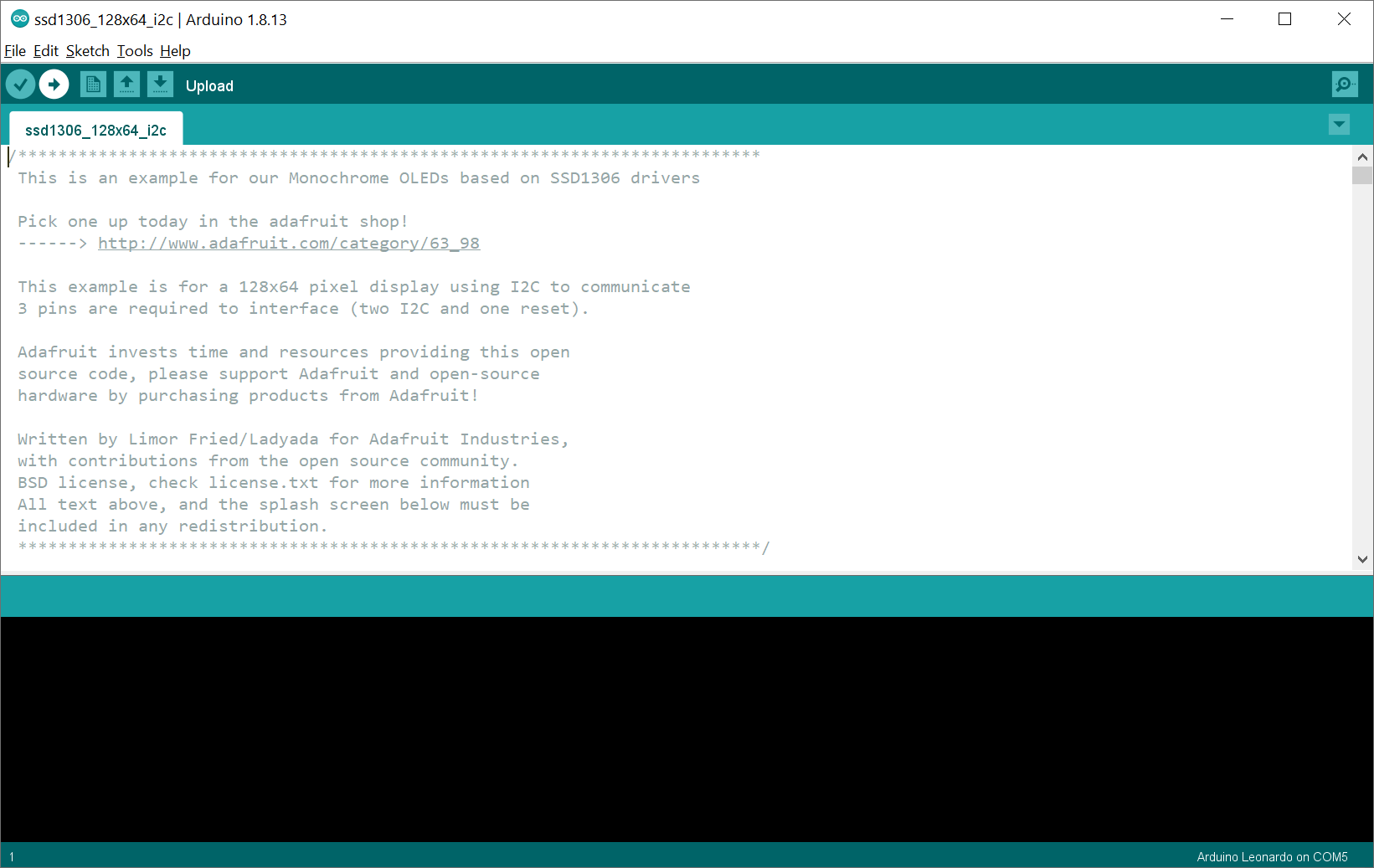
Step 2: Compile and upload the example
Now, compile and upload the example.
Step 3: Watch the demo
Once the code has compiled and uploaded, it should look something like this:
Video Running the demo ssd1306_128x64_i2c . Parts of this video are sped up 4x.
If you’re curious how they rendered something, please do look over the source code. There is nothing magic here and reading the code may help inform your future prototypes!
The Adafruit GFX Library
Now that we’ve got our OLED display wired up correctly and tested that it’s working, let’s talk about how to draw to the screen.
To provide a common API for drawing across all Adafruit LCD and OLED displays, Adafruit created a general-purpose graphics rendering library, called Adafruit GFX. Put simply, rather than having to individually turn on/off OLEDs in the OLED matrix—which would be tedious (though perhaps a useful learning exercise)—the Adafruit GFX library provides higher level drawing routines to do this for you, like drawing rectangles, circles, text, and bitmaps.
NOTE:
You certainly do not have to use the Adafruit SSD1306 and GFX libraries to use OLED displays. There are many tutorials online that describe how to directly interface with the SSD1306 OLED driver and create drawing routines. For example, this “Getting Started With OLED Displays” by JayconSystems on Instructables. Remember, the Adafruit engineers simply built their libraries to make it easier to program OLEDs… and we’re thankful! But you could also follow the SSD1306 and I 2 C specs and build your own libraries!
Coordinate system and pixels
If you’re familiar with graphics APIs in other programming frameworks—like C#’s System.Drawing library, Processing’s Java drawing library, p5js’ JavaScript drawing library, etc.—the Adafruit GFX library works much the same (at a high level).
The black-and-white OLED consists of a matrix of OLEDS, called pixels, which can be individually addressed to turn on/off (or, in the case of colored displays, to control individual RGB OLEDs to create colors). As with all other drawing libraries, the coordinate system for these pixels places the origin (0,0) at the top-left corner with the x-axis increasing to the right and the y-axis increasing down.
![]() Figure An overview of the 128×64 matrix of LEDs—we call each LED a “pixel”. We’ve found that students sometimes flip the y-axis in their minds. So, make sure to note how the origin starts at (0,0) and the x-axis increases to the right and the y-axis increases down. Image created in PowerPoint and uses images from Fritzing and the Adafruit GFX tutorial.
Figure An overview of the 128×64 matrix of LEDs—we call each LED a “pixel”. We’ve found that students sometimes flip the y-axis in their minds. So, make sure to note how the origin starts at (0,0) and the x-axis increases to the right and the y-axis increases down. Image created in PowerPoint and uses images from Fritzing and the Adafruit GFX tutorial.
Thus, to turn “on” the LED at pixel (18, 6) using Adafruit GFX, we would write: drawPixel(18, 6, SSD1306_WHITE) . For black-and-white displays, the last argument can be either SSD1306_WHITE to draw a white pixel or SSD1306_BLACK to draw a black pixel (these parameters are defined in Adafruit_SSD1306.h). For color displays, you can instead pass in an unsigned 16-bit value representing RGB colors (see docs).
Drawing subsystem
Below, we describe how to draw shapes, text, and bitmaps. Importantly, when you call any of the drawing routines—from drawLine to drawTriangle —you are not drawing directly to the OLED display. Instead, you are drawing to an offscreen buffer handled by the SSD1306 driver. So, after you call your drawing routines, you must then call the void Adafruit_SSD1306::display() function to push the data from RAM to the display. We’ll show how to do this step-by-step in our examples below.
In short, the drawing pipeline looks like this:
Now, because we are drawing the exact same thing on every loop() call, we could just as well put this drawing code into setup() and have it draw once and only once (the graphic content will persist).
However, for practical purposes, we always want to put our drawing methods in loop() because we want so support dynamic graphics, which are animated (e.g., graphics that change over time) and/or responsive (e.g., graphics that change in response to input).
Drawing shapes
The Adafruit GFX library current supports drawing lines, rectangles, circles, rounded rectangles, and triangles. For all shapes, you can draw an outlined version (e.g., drawRect ) or a filled version (e.g., fillRect ). The images below are drawn from the Adafruit GFX tutorial.
| Shape and API call | Output |
|---|---|
| Lines void drawLine(uint16_t x0, uint16_t y0, uint16_t x1, uint16_t y1, uint16_t color); |
 drawLine(5, 10, 3, 19, SSD1306_WHITE) drawLine(5, 10, 3, 19, SSD1306_WHITE) |
| Rectangles void drawRect(uint16_t x0, uint16_t y0, uint16_t w, uint16_t h, uint16_t color); |
Drawing custom shapes
You can, of course, create custom shapes either by cleverly combining shape primitives (e.g., a rectangle and a triangle to make a basic house) or by implementing your own drawing algorithm and calling drawPixel . The drawPixel API looks like:
| Shape and API call | Output |
|---|---|
| Pixels void drawPixel(uint16_t x, uint16_t y, uint16_t color); |
 drawPixel(0, 0, SSD1306_WHITE) drawPixel(0, 0, SSD1306_WHITE) drawPixel(18, 6, SSD1306_WHITE) drawPixel(6, 13, SSD1306_WHITE) |
Optimized vertical and horizontal line drawing
If you are drawing purely vertical or horizontal lines, then you can use optimized line-drawing functions that avoid angular calculations. For example, we use drawFastVLine in our analog graphing demos below.
For more information and examples, see the Basic Drawing section of Last Minute Engineer’s OLED display tutorial.
Drawing text
There are two methods to render text: drawing a single character with drawChar and using the print rendering subsystem, which mimics the familiar Serial.print() functionality covered in our Intro to Arduino series here.
Method 1: drawChar
To draw a single character, you specify a (x, y) location, the character, the foreground and background color, and a size. By default, characters are 5×8 pixels but an optional size parameter (the last argument) can be passed to scale the font (e.g., a size of 2 will render 10×16 pixels per character).
| Text API call | Output |
|---|---|
| Char void drawChar(uint16_t x, uint16_t y, char c, uint16_t color, uint16_t bg, uint8_t size); |
 drawChar(3, 4, ‘A’, SSD1306_WHITE, SSD1306_BLACK, 1) drawChar(3, 4, ‘A’, SSD1306_WHITE, SSD1306_BLACK, 1) |
Method 2: Print rendering
The more common and feature-rich method to draw text is via the print subsystem. Interestingly, the Adafruit_GFX class actually extends the Print class from the Arduino core library. You can view the Serial.print() docs here; the API is the same for the OLED.
Rather than call Serial.print(«Hello World») , however, with the OLED display and Adafruit GFX library, you would call _display.print(«Hello World») . Here, _display is the Adafruit_SSD1306 object.
To use the OLED’s print functionality, you can first set optional parameters such as the text color, size, and wrapping:
Then, to position the text, you set the print cursor with:
Finally, to print the text at that cursor position, you can call any of the standard Serial.print methods, including this subset:
See the Serial.print() docs or the Print.h library for more on the print API or read on for an example.
Centering text
In creative coding, visualization, and game dev, we often want to center or otherwise align text. To do so, we need to measure it. Fortunately, the Adafruit GFX library has a method called getTextBounds that does just that!
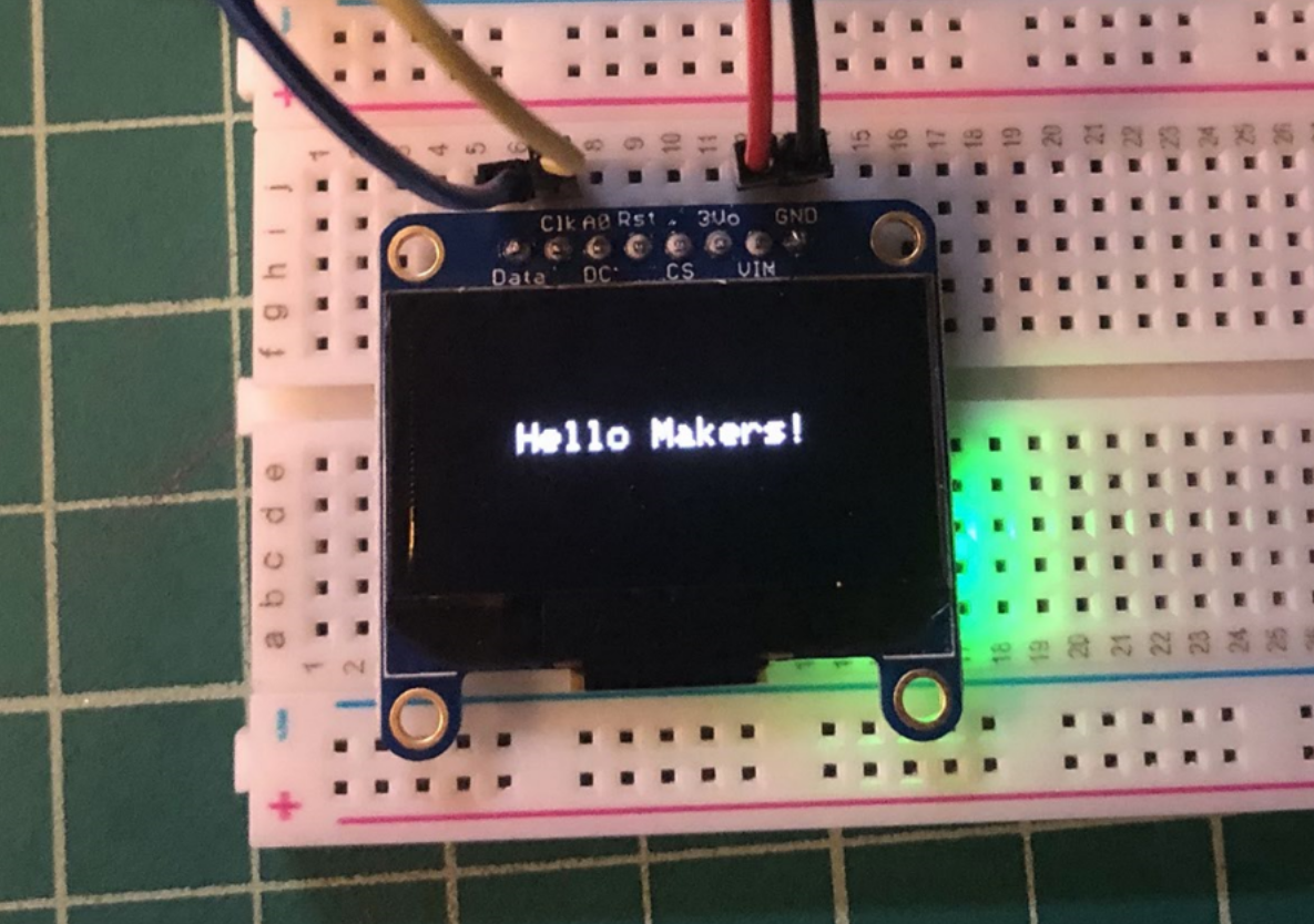
For example, in our HelloWorld.ino example, we center the text “Hello Makers!” both vertically and horizontally on the OLED screen. The key excerpt is here:
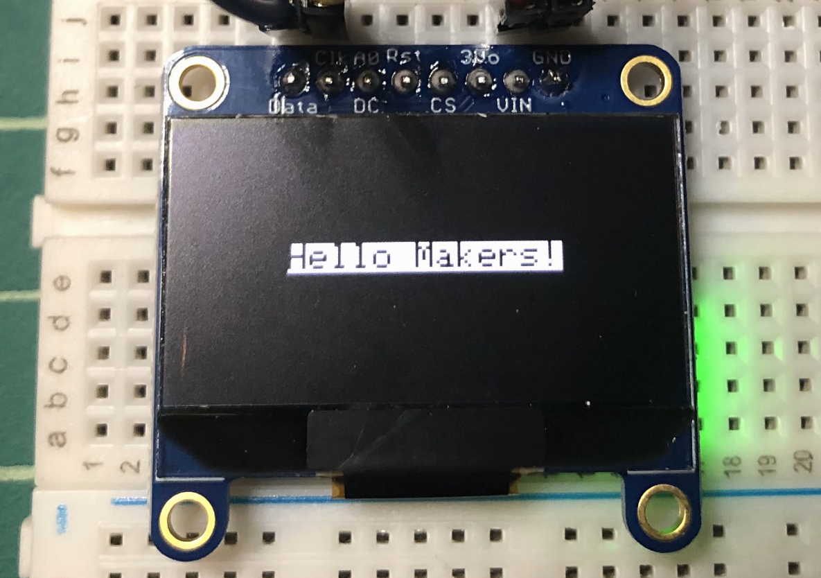
Inverting text
We can also invert the text simply by switching the colors in setTextColor(uint16_t color, uint16_t backgroundcolor) . So, to draw black text on a white background, we would write _display.setTextColor(BLACK, WHITE);
| setTextColor(WHITE, BLACK) | setTextColor(BLACK, WHITE) |
|---|---|
 |
 |
Drawing the embedded font graphics
You can draw the embedded font graphics either using drawChar or, similar to Serial.write() , the Adafruit GFX library also supports the write() function.
While you can also use either drawChar or write , the latter uses the currently set setText parameters like setTextSize and setTextColor —which is helpful. Below, I’m printing out all of the glyphs embedded in the default font, which includes embedded graphics like smiley faces, hearts, spades, etc.
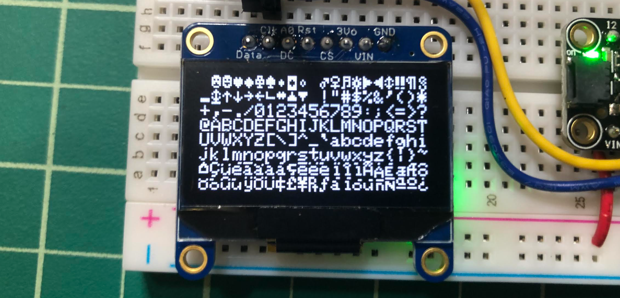 Figure. Drawing the embedded glyphs in the default font using _display.write() . This code is called DrawAllChars.ino in our GitHub.
To draw a happy face—which is char index 2 in the middle of the screen, for example, we could use drawChar :
Or we could also use the write() method:
Here’s an example iterating through all of the glyphs individually, which demonstrates the code above. Again, you can use either drawChar or write and I demonstrate both in DrawChar.ino
Video A demonstration of DrawChar.ino showing how to draw the embedded graphics from the default font.
Loading custom fonts
In addition to the default fixed-size, mono-spaced font, you can also load and render an alternative font. See the “Loading Fonts” section of the Adafruit GFX tutorial.
You can also make your own font or custom symbols for your font. See the Adafruit tutorial: “Creating Custom Symbol Fonts for Adafruit GFX Library”.
Drawing bitmaps
Finally, you can load and render custom bitmaps on the display. See “Displaying Bitmaps” on Last Minute Engineers.
Adafruit GFX Resources
Before moving forward, we strongly encourage you to read the official Adafruit GFX tutorial and the “Last Minute Engineers” OLED tutorial—both offer great overviews of the Adafruit GFX library and how to display text, draw shapes, and load and display bitmaps.
In addition, you can:
View the Adafruit GFX library source code here, including the Adafruit_GFX.h, which shows the available API. Yes, depending on your familiarity with C++ and reading .h files, this might be intimidating or overwhelming—but it’s important to demystify these libraries. They are just source code that devs wrote. And, with experience, you could too!
Examine our own OLED examples here, including the Hello World example mentioned above, a simple animation example called BallBounce, an object-oriented version of this animation using the Shape.hpp class from the Makeability Lab Arduino library, and simple games such as a collision test, Pong, and Flappy Bird. We’ll go over some of these below.
Let’s make stuff!
In this part of the lesson, we are going to make a variety of OLED-based creations. This should be fun! As mentioned, we have a GitHub repo of OLED examples, some of which we describe below.
Activity: draw shapes and text
First, to get a feel for and experience with the Adafruit GFX API and the coordinate system, let’s simply draw some text and shapes to the screen. You get to choose what you want you want to draw and where. Think of it like abstract shape art!
Remember, in loop() , you need to:
I made a version, called SimpleDrawingDemo.ino that draws shapes of random sizes and locations on each frame but you could do something even simpler (or more complex)!
Video A demonstration of SimpleDrawingDemo.ino.
Shape drawing prototyping journal activity
For your prototyping journals, create your own shape/text drawing demo. Take a picture or, if there is animation, record a short video or animated gif. In your journals, link to the code, insert the pictures/videos, and reflect on what you learned.
Activity: draw a bouncing ball
Now that we’ve gained some familiarity with the drawing API and graphics pipeline, let’s learn a bit about animation.
We are going to draw a simple bouncing ball around the screen. Bouncing or reflecting objects are one of the key components of many games, including Pong, Arkanoid, etc.
To create a bouncing ball, we need to:
- Track the x,y location of the ball across frames
- Set a x,y speed in pixels per frame—that is, how much the does the ball move per frame? For smoother animation, we could track x,y speed in terms of time (e.g., pixels/second); however, this is slightly more complicated (e.g., it requires tracking timestamps in the code, computing time deltas, etc.). For our purposes, tracking x,y speed in terms of pixels/frame is fine.
- Check for collisions when the ball collides with the ceiling, floor, or walls of the screen. When a collision occurs, simply reverse the direction of the ball.
- Draw the circle at the given x,y location.
Prototyping ideas with p5js
Here’s a demo of a bouncing ball we made in p5js. Sometimes, it’s useful to prototype a visualization or game idea in a rapid programming environment like p5js or Processing before coding it up in C++ for Arduino (and it’s easier to debug in those environments as well). You can edit and play with this demo in your browser here using the p5js online editor.
Video. A video of the Ball Bounce demo created in p5js. You can edit the source code and run it live in the p5js online editor here. Alternatively, you can view the source in our p5js GitHub repo.
C++ implementation using Adafruit GFX
For the C++ implementation using the Adafruit GFX library and Arduino, the key bits of code are excerpted below. The overall implementation is quite similar to the p5js version. Make sure you read over this code carefully and understand it.
Again, rather than, say “miles per hour” or “pixels per second”, we’ve defined speed as “pixels per frame”—that is, how many pixels does the object move per frame. If we set _xSpeed to 5 and _ySpeed to 0, then the ball would move 5 x pixels per frame (and simply bounce back and forth from the left side of the screen to the right and back again).
You can view the full code on GitHub as BallBounce.ino.
Bitmap bounce
We also have a similar “bounce” demo, called BitmapBounce.ino, that uses a bitmap rather than a graphic primitive. To create the the bitmap byte dump, we used this image2cpp tool on this Makeability Lab logo.
Video. A video of BitmapBounce.ino.
Animation prototyping journal activity
For your prototyping journals, create a custom animation demo, record a short video or animated gif, link to the code, and reflect on what you learned. As one simple example, change the object bouncing around from a circle to a rectangle. If you want something more challenging, try bouncing a triangle around the screen and using the entry angle and triangle angles to properly calculate the reflection (it’s probably easiest to do this using vector calculations). Or you could use the drawLine method to animate rain fall similar to this Purple Rain video by the Coding Train. While this was made for p5js, it would fairly straightforward to translate to Arduino and the Adafruit GFX library.
Activity: interactive graphics
Finally, for our last activity, let’s make a few interactive prototypes—that is, graphics that respond to digital or analog input. Interactivity captures the true essence of physical computing. And for an HCI professor like me, this is where the joy really begins!
Demo 1: Setting ball size based on analog input
We’ll start with changing a shape’s size based on sensor input. While you can use whatever sensor you want, for this demonstration, we will use our ole trusty potentiometer hooked up to A0 .
The OLED + pot circuit
Here’s the circuit. Same as before but we’ve added a 10K potentiometer.
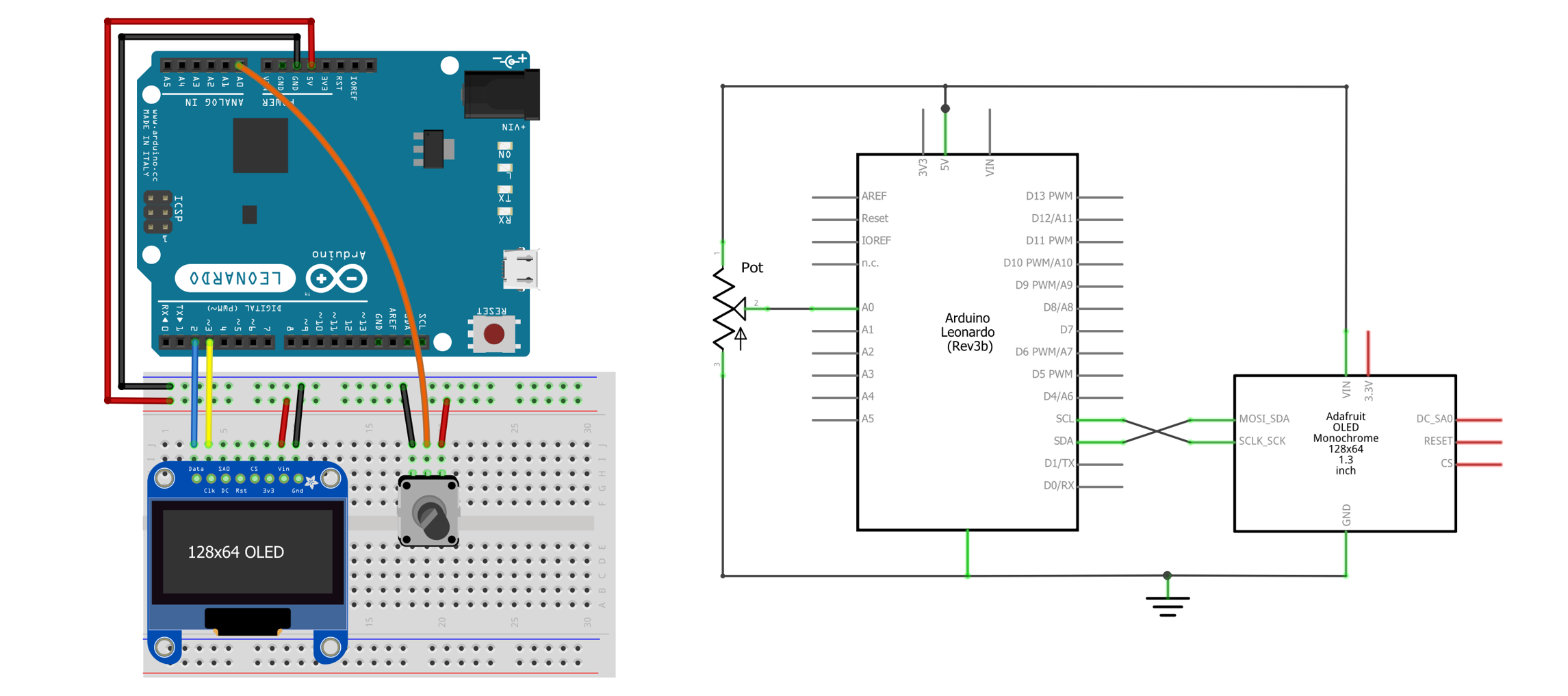 Figure A basic OLED circuit with potentiometer input on A0 .
The OLED + pot code
The code is simple: read the analog input and use this to set the circle’s radius.
You can view the full code on GitHub as AnalogBallSize.ino.
Video. A video of AnalogBallSize.ino.
Demo 2: Setting ball location based on analog input
Now let’s hook up two analog inputs to control the x,y location of the circle rather than the size. In this case, we’ll use two potentiometers. The wiring diagram is below.
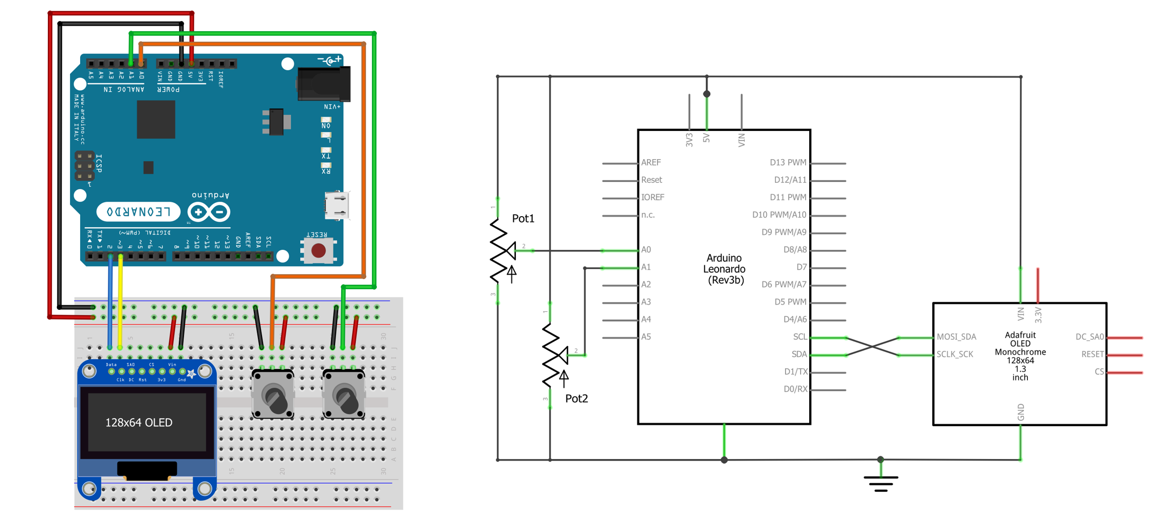 Figure The wiring and circuit diagram for two potentiometers and the OLED display.
For the code, it’s very similar to AnalogBallSize.ino. But we translate the analogRead values to x and y locations:
You can view the full code on GitHub as AnalogBallLocation.ino.
Video A demonstration of AnalogBallLocation.ino using potentiometers on A0 and A1 .
Demo 3: Basic real-time analog graph
One of the most famous Arduino + Processing demos is the real-time analog sensor graph (link): the Arduino reads sensor data using analogRead then transmits it to the computer using Serial.println() where it is parsed and graphed using Processing.
With the OLED display and the Adafruit GFX library, we can easily recreate this entirely on the Arduino!
Как подключить OLED I2C дисплей к ARDUINO
Привет! Будучи любителем — энтузиастом электроники, я уверен, что всё что мы делаем – радиоэлектронные игрушки – самоделки, или большие проекты, все это от любопытства и лени. Любопытство стремится понять и постичь необъятное, не познанное, разобраться, как оно там работает, чего делает, как двигается. А лень изобретает, чтобы такого придумать, чтобы не вставать, не подходить, не поднимать, не запачкаться или еще чего ни будь важное.
Так как видеть информацию, это лучше, чем разбираться чего там сейчас должно произойти в нашем устройстве, или уже произошло, или происходит, мы обязательно захотим получить эту самую полезную информацию от наших микроконтроллеров, датчиков, или прочих устройств. А получать, я во всяком случае, хочу какие-либо сообщения, вроде вопросов, предупреждений, напоминаний, смайликов, звездочек, сердечек и тому подобное.
Для тех, у кого тоже возникло подобное желание, — вот краткое руководство по подключению и проверке маленьких и не дорогих дисплеев OLED.
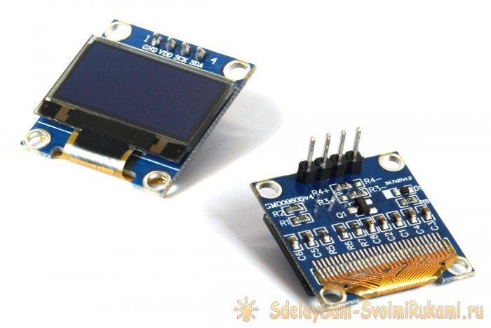
Далее речь пойдет об одной из широко доступных для радиолюбителей моделях OLED дисплеев, управляемых чипом SSD1306, с размером экрана 0,96-дюймов и разрешением 128*64 или 128*32 точки. Эти дисплеи идеально подходят для не больших радиолюбительских конструкций и самоделок.
Шаг 1: Основные понятия
- OLED это Organic Light-Emitting Diode, т.е., полупроводниковый прибор из органических соединений, который начинает излучать свет при прохождении через него электрического тока.
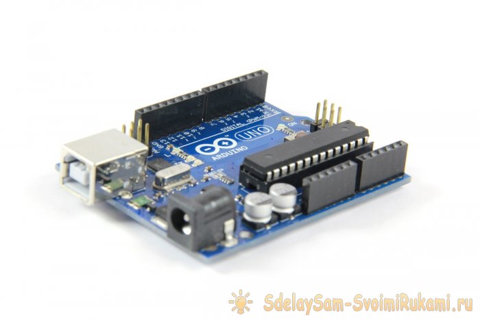
- ARDUINO — это платформа для обучения и построения систем автоматики и робототехники.
- ArduinoIDE — среда разработки. Это бесплатная программа для программирования Arduino.
- I2C – Inter-Integrated Circuits, межмикросхемная линия связи.
- Скетч, он же, код, он же программа — терминология Arduino.
Шаг 2: Комплектующие
- 1. Сам OLED дисплей 0,96” (можно купить на Aliexpress или Ebay, — долго, но дешево!).
- 2. Arduino UNO / Nano (там же где дисплей).
- 3. Соединительные провода (там же).
- 4. Компьютер или ноутбук с установленной ArduinoIDE.
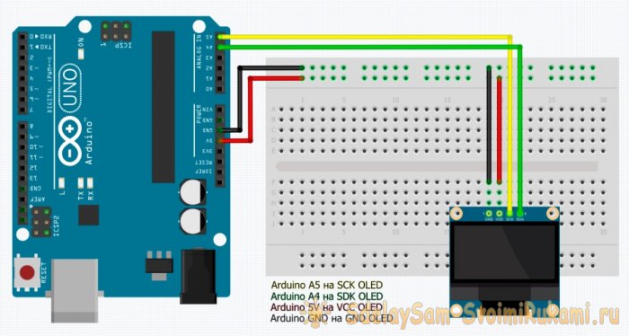
Шаг 3: Подключение дисплея
- Vcc — 5V
- GND — GND
- SDA — A4
- SCL — A5
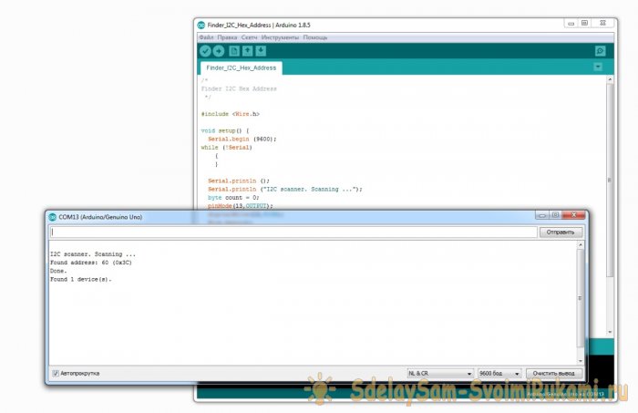
Шаг 4: Сканер I2C
Каждое устройство на шине I2C имеет шестнадцатеричный адрес, поменять нельзя, он вшит намертво, каждый ответственный производитель должен где-то на корпусе или в инструкции указать его. Бывают модули с переключателями и перемычками, которыми можно изменить адрес, но… если устройства дешевые, до безобразия, то производитель может и не удосужиться заниматься такой мелочью, поэтому его придется определять самостоятельно.
Всего на шине может использоваться до 127 адресов — 119 для устройств и 8 адресов служебных. Общение ведется по этим адресам. Есть главный, он же Master, а есть ведомый, он же Slave, — Мастера запрашивают, ведомые отвечают, все просто.
Поскольку на нашем OLED-дисплей используется протокол связи I2C, а адрес может быть и не указан, мы сами попробуем узнать этот самый адрес.
Это можно сделать, загрузив коротенький скетч на свою плату Arduino с подключенным OLED. НО!
Не торопитесь сразу заливать скетч в Arduino! Давайте для начала загрузим «драйвера», т.е. подключим библиотеки, а для этого сразу перейдем к «Шагу №5», а затем вернемся и продолжим.
Шаг 4: Продолжение:
Шаг 5: Загрузка и подключение библиотек
- 1. В ArduinoIDE идем в меню Скетч / Sketch.
- 2. Выбираем «Включить библиотеки» / Include Libraries.
- 3.Выбираем «Управление библиотеками» / Managed Libraries.
- 4. Находим ADAFRUIT GFX и устанавливаем их.
- 5. Находим ADAFRUIT SSD1306 и устанавливаем их.
Шаг 6: Тестирование дисплея
Откройте файл Adafruit_SSD1306.h в текстовом редакторе и найдите строки:
Должно получиться так:
Если снова ошибка – необходимо проверить правильность соединений.
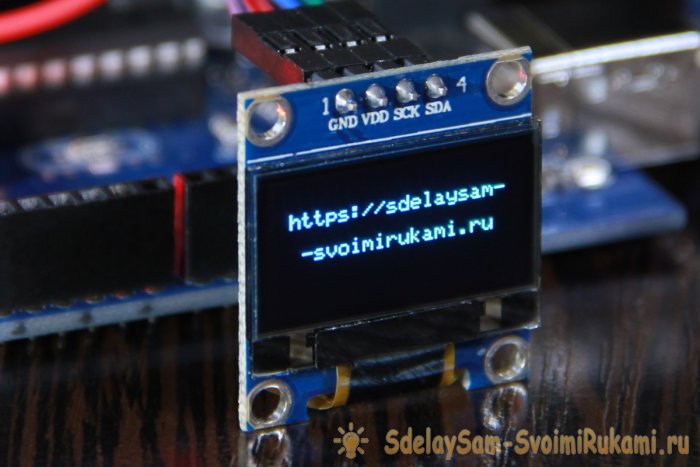
После окончания загрузки вы увидите тестовую анимацию на экране, это означает, что вы успешно настроили свой OLED дисплей.
Когда вы вдоволь насладитесь сей анимацией, можете переходить к следующему шагу.
Шаг 7: Пишем свое собственное сообщение
Для написания собственного сообщения, сначала создадим новый скетч в среде программирования ArduinoIDE.
В заголовке мы подключаем 4 библиотеки:
Затем пишем протокол сброса:
В VOID SETUP указываем шестнадцатеричный адрес нашего дисплея 0x3C, который мы узнали на «Шаге №4».
Затем, инициализируем дисплей и очищаем его:
Далее в VOID LOOP пишем основной код, то есть наше сообщение, которое хотим отобразить на дисплее.
Для этого описываем размер текста, цвет текста, позицию курсора, и наконец, выводим сообщение с помощью команды println:
Использование OLED дисплея совместно с Arduino
Надоело использовать символьные ЖК-дисплей в своих проектах Arduino? Что ж! Они действительно уходят в прошлое. Используйте в своих проектах современные OLED (органические светодиоды) дисплеи! Они легкие, тонкие, теоретически гибкие и дают более яркое и четкое изображение.
Модуль OLED диспля на основе драйвера SSD1306
В основе модуля лежит мощный однокристальный CMOS контроллер SSD1306. Он может общаться с микроконтроллером несколькими способами, включая I2C и SPI .
Протокол SPI, как правило, быстрее, чем I2C, но требует большего количества контактов ввода/вывода микроконтроллера. В то время как I2C требует только два контакта и может использоваться совместно с другими периферийными устройствами I2C. Это компромисс между экономией выводов и скоростью.

Благодаря универсальности контроллера SSD1306, модуль поставляется в разных размерах и цветах: например, 128×64, 128 × 32, с белыми OLED, синими OLED и двухцветными OLED. Хорошей новостью является то, что все эти дисплеи взаимозаменяемы.

Требование к источнику питания
Для работы OLED-дисплею не нужна подсветка, поскольку он излучает свой собственный свет. Именно поэтому дисплей имеет такой высокий контраст, чрезвычайно широкий угол обзора и может отображать глубокий уровень черного цвета.
Отсутствие подсветки значительно снижает ток потребления. В среднем дисплей потребляет около 20 мА , хотя это зависит от того, какая часть дисплея задействована.
Рабочее напряжение контроллера SSD1306 составляет от 1,65 до 3,3 В, в то время как для OLED-панели требуется напряжение питания от 7 до 15 В. Все эти различные требования к питанию решаются путем использования схемы Charge Pump. Это позволяет легко подключить модуль к Arduino или любому 5-вольтовому логическому микроконтроллеру без использования преобразователя логического уровня.
Организация памяти SSD1306
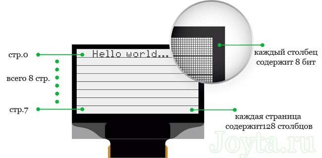
Независимо от размера OLED модуля драйвер SSD1306 имеет встроенную память объемом 1 КБ (GDDRAM). Эта область памяти разбита на 8 страниц (от 0 до 7). Каждая страница содержит 128 столбцов / сегментов (блок от 0 до 127). И каждый столбец может хранить 8 бит данных (от 0 до 7):
8 страниц x 128 сегментов x 8 бит данных = 8192 бит = 1024 байт = 1 Кб памяти

Каждый бит представляет собой определенный OLED пиксель на экране, который может быть включен или выключен программно.
Экран 128 × 64 OLED отображает все содержимое ОЗУ, тогда как экран 128 × 32 OLED отображает только 4 страницы (половину содержимого) ОЗУ.
Распиновка модуля дисплея OLED
Прежде чем перейти к написанию кода и рассмотрению примеров, давайте сначала посмотрим на распиновку OLED модуля:

- GND — вывод должен быть подключен к земле Arduino
- VCC — вывод питания для дисплея, к которому мы подключаем 5-вольтный контакт на Arduino
- SCL — вывод синхронизации для интерфейса I2C
- SDA — вывод данных для интерфейса I2C
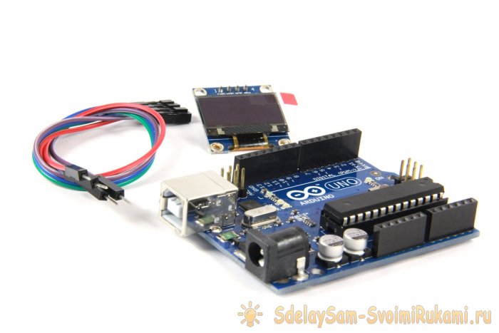
Подключение модуля OLED к Arduino Uno
Прежде чем мы перейдем к загрузке кода и отправке данных на дисплей, давайте подключим дисплей к Arduino Uno.
Схема подключения довольно проста. Начните с подключения контакта VCC к выходу 5V на Arduino и GND к земле. Теперь остались выводы, которые используются для связи по I2C. Обратите внимание, что каждая плата Arduino имеет разные контакты I2C.
На платах Arduino с маркировкой R3 SDA (линия передачи данных) и SCL (линия синхронизации) находятся на разъемах рядом с выводом AREF. Они также известны как A5 (SCL) и A4 (SDA).
Если у вас MEGA, контакты будут другие! Используйте цифровые 21 (SCL) и 20 (SDA).

На следующей схеме показано как все должно быть подключено:

Установка библиотеки для модуля OLED
Контроллер SSD1306 OLED дисплея имеет гибкие, но сложные драйверы. Для использования контроллера SSD1306 необходимы огромные знания по адресации памяти. К счастью, была написана библиотека Adafruit SSD1306, которая позволяет довольно простыми и понятными командами управлять OLED дисплеем.
Чтобы установить библиотеку, перейдите в раздел Sketch > Include Library > Manage Libraries…. Подождите, пока менеджер библиотеки загрузит индекс библиотек и обновит список установленных библиотек.

Отфильтруйте результаты поиска, введя adafruit ssd1306. Там должна быть пара записей. Ищите Adafruit SSD1306 от Adafruit. Нажмите на эту запись, а затем выберите Установить.

Библиотека Adafruit SSD1306 представляет собой аппаратную библиотеку, которая выполняет функции более низкого уровня. Она должна быть сопряжена с библиотекой Adafruit GFX для отображения графических примитивов, таких как точки, линии, круги, прямоугольники и т. д. Также установите и эту библиотеку.

Известная проблема с контроллером SSD1306
Хотя SSD1306 имеет встроенный GDDRAM для экрана, мы не можем прочитать его содержимое (согласно Adafruit). Следовательно, невозможно управлять экранным буфером для выполнения математических операций.
В качестве альтернативы библиотека выделяет 1 КБ (128 × 64) / 8 бит) памяти ATmega328P в качестве буфера. Таким образом, появляется возможность манипулировать экранным буфером и затем выполнять массовую передачу из памяти ATmega328P во внутреннюю память контроллера SSD1306.
Модификация библиотеки Adafruit SSD1306
Библиотека Adafruit SSD1306 не настроена для 128 × 64 OLED-дисплеев (используемый в данной статье). Размер экрана необходимо изменить в заголовочном файле Adafruit_SSD1306.h.
Если этого не сделать, то при компиляции мы получим сообщение об ошибке #error (“Height incorrect, please fix Adafruit_SSD1306.h!”):

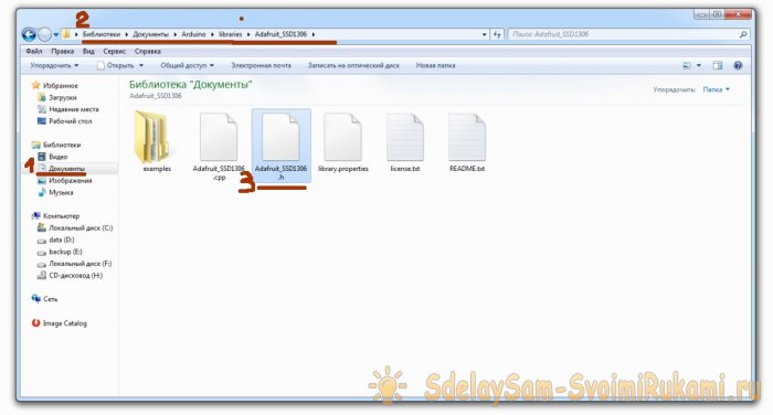
Чтобы изменить заголовочный файл Adafruit_SSD1306.h, откройте Документы > Arduino. Теперь перейдите в библиотеку Adafruit_SSD1306:
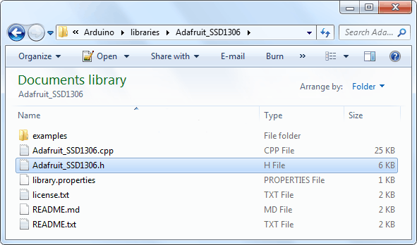
Откройте файл Adafruit_SSD1306.h в текстовом редакторе (например, notepad++). Прокрутите файл вниз, чтобы найти раздел с дисплеями SSD1306 или сразу перейдите к строке №73. Закомментируйте #define SSD1306_128_32 и раскомментируйте #define SSD1306_128_64, чтобы код в этом разделе выглядел следующим образом:

Вот и все. Теперь сохраните файл и перезапустите вашу Arduino IDE.
Скетч для отображения текста на OLED
Теперь самое интересное!
Следующий тестовый скетч напечатает «Hello World!» сообщение на дисплее. Он также включает:
- Отображение перевернутого текста
- Отображение номеров
- Отображение чисел (Hex, Dec)
- Отображение ASCII символов
- Прокрутка текста по горизонтали и вертикали
- Прокрутка части дисплея
Это даст вам полное представление о том, как использовать OLED-дисплей, и может послужить основой для реализации своих проектов.
При компиляции кода в среде IDE появиться предупреждение о нехватке памяти. Это связано с тем, что библиотека выделяет 1 КБ памяти ATmega328P в качестве буфера отображения. Вы можете игнорировать это.
Скетч начинается с подключения четырех библиотек, а именно. SPI.h, Wire.h, Adafruit_GFX.h и Adafruit_SSD1306.h. Хотя библиотека SPI.h не требуется для I2C OLED-дисплеев, нам нужно добавить ее для компиляции нашей программы:
Далее нам нужно создать объект Adafruit_SSD1306.h. Конструктор Adafruit_SSD1306 принимает номер контакта Arduino, к которому подключен вывод сброса дисплея. Поскольку используемый нами OLED-дисплей не имеет вывода RESET, мы отправим в конструктор -1 , чтобы ни один из выводов Arduino не использовался в качестве сброса для дисплея.
В функции setup() нам нужно инициализировать объект OLED с помощью функции begin(). Функция принимает два параметра. Первый параметр SSD1306_SWITCHCAPVCC включает схему charge pump, а второй параметр устанавливает адрес I2C OLED дисплея. I2C адрес такого OLED модуля обычно равен 0x3C.
Далее мы очищаем буфер перед печатью нашего первого сообщения:
Отображение простого текста (Hello World)

Для отображения текста на экране нам нужно установить размер шрифта. Это может быть сделано путем вызова setTextSize() и передачи размера шрифта (начиная с 1) в качестве параметра.
Далее нам нужно установить цвет шрифта, вызвав функцию setTextColor(). Передайте параметр WHITE для темного фона и BLACK для яркого фона. Теперь перед печатью сообщения нам нужно установить позицию курсора, вызвав функцию setCursor (X, Y).
Пиксели на экране адресуются по горизонтальным (X) и вертикальным (Y) координатам. Система координат размещает начало координат (0,0) в верхнем левом углу, причем положительный X увеличивается вправо, а положительный Y увеличивается вниз.
Мы можем использовать функцию print() или println() для печати сообщения на экране так же, как мы печатаем данные на последовательном мониторе. Помните, println () переместит курсор на новую строку.
Чтобы библиотека могла выполнять чрезвычайно быстрые математические операции с буфером экрана (более 100 кадров в секунду), вызовы функций печати не сразу передают содержимое экранного буфера в SSD1306 контроллер.
Для этого требуется команда display(), чтобы дать указание библиотеке выполнить массовую передачу из экранного буфера ATmega328P во внутреннюю память контроллера SSD1306. Как только память будет перенесена, на OLED-дисплее появятся пиксели, соответствующие экранному буферу.
Инверсия сообщения

Для выполнения инверсии мы снова вызываем функцию setTextColor(FontColor,BackgroundColor). Если вы обратили внимание, то вы заметите, что до этого мы передали только один параметр этой функции, но теперь мы передаем два параметра.
Изменение размера шрифта

Ранее мы вызывали функцию setTextSize() для установки размера шрифта и передавали 1 в качестве параметра. Вы можете использовать эту функцию для масштабирования шрифта, передавая любое неотрицательное целое число.
Символы отображаются в соотношении 7:10. Это означает, что при передаче размера шрифта 1 текст будет отображаться с разрешением 7 × 10 пикселей на символ, при передаче 2 будет отображаться текст с разрешением 14 × 20 пикселей на символ и т. д.
Отображение чисел

Числа могут быть отображены на OLED дисплее путем вызова функций print() или println().
Указание базиса чисел

Функции print() и println() имеет второй необязательный параметр , который определяет базу (формат). Допустимые значения:
- BIN (двоичное или базовое 2),
- OCT (восьмеричное или базовое 8),
- DEC (десятичное или базовое 10),
- HEX (шестнадцатеричное или базовое 16).
Для чисел с плавающей запятой этот параметр указывает количество десятичных знаков. Например:
- print(78, BIN) — дает «1001110»
- print(78, OCT) — дает «116»
- print(78, DEC) — дает «78»
- print(78, HEX) — дает «4E»
- println(1.23456, 0) — дает «1»
- println(1.23456, 2) — дает «1.23»
- println(1.23456, 4) — дает «1.2346»
Отображение ASCII символов

Функции print() и println() отправляют данные на дисплей в виде удобочитаемого текста ASCII, а функция write() отправляет двоичные данные. Таким образом, вы можете использовать эту функцию для отображения символов ASCII. В нашем примере отправка числа 3 будет отображать символ сердца.
Полноэкранная прокрутка
Вы можете прокручивать дисплей по горизонтали, вызывая функции startscrollright() и startscrollleft(), и по диагонали, вызывая startscrolldiagright() и startscrolldiagleft(). Все эти функции принимают два параметра, а именно: начальная страница и конечная страница.
Поскольку на дисплее отображается восемь страниц от 0 до 7, вы можете прокручивать весь экран, прокручивая все страницы, то есть передавая параметры 0x00 и 0x07. Чтобы остановить отображение прокрутки вы можете использовать функцию stopscroll().
Прокрутка определенной части
Иногда у нас нет необходимости в прокрутке всей странице. В этом случае мы можете сделать это, передав стартовую страницу и информацию об остановке страницы функциям прокрутки.
Поскольку на дисплее отображается восемь страниц от 0 до 7, мы можете прокрутить некоторую часть экрана, передавая конкретные номера страниц в качестве параметров.
В нашем примере мы передали оба параметра как 0x00. Это позволит прокрутить только первую страницу (первые 8 строк) дисплея.
Код Arduino — базовые фигуры
В этом примере рассмотрим некоторые базовые фигуры. Этот скетч демонстрирует множество функций рисования, включая прямоугольник, скругленный прямоугольник, круг и треугольник.
Большая часть кода (включая библиотеки и отображение инициализации) такая же, как в примере выше, за исключением фрагментов кода для рисования основных фигур.
Рисование прямоугольника


Вы можете нарисовать на дисплее прямоугольник с помощью функции drawRect(). Функция принимает пять параметров, а именно: координаты X и Y, ширина, высота и цвет. На самом деле эта функция рисует не закрашенный прямоугольник с границей в 1 пиксель. Вы можете нарисовать закрашенный прямоугольник, используя функцию fillRect().
Рисование скругленный прямоугольник


Вы можете нарисовать на дисплее скругленный прямоугольник с помощью функции drawRoundRect(). Эта функция принимает те же параметры, что и функция drawRect(), за исключением одного дополнительного параметра — радиуса скругления угла. На самом деле эта функция рисует не закрашенный скругленный прямоугольник с границей в 1 пиксель. Вы можете нарисовать закрашенный круглый прямоугольник, используя функцию fillRoundRect().
Рисование круга


Вы можете нарисовать круг на дисплее с помощью функции drawCircle(). Функция принимает четыре параметра, а именно: координата центра X и Y, радиус и цвет. Эта функция рисует не закрашенный круг с границей в 1 пиксель. Вы можете нарисовать закрашенный круг, используя функцию fillCircle().
Рисование треугольника


Вы можете нарисовать треугольник на дисплее с помощью функции drawTriangle(). Функция принимает семь параметров, а именно: X и Y координаты (x0, y0, x1, y1, x2, y2) вершин треугольника и цвета. (x0, y0) представляет верхнюю вершину, (x1, y1) представляет левую вершину и (x2, y2) представляет правую вершину.
Эта функция рисует не закрашенный треугольник с границей в 1 пиксель. Вы можете нарисовать закрашенный треугольник, используя функцию fillTriangle().