
MIDI On The VS1053 Module
There are synthesizer modules available that connect directly to a microcontroller on a breadboard. VSLI’s VS1053 MP3 decoder and MIDI synthesizer is a good example. Sparkfun and Adafruit both make breakout boards or Arduino shields for this component, such as Sparkfun’s MP3 Player shield or Musical Instrument shield, or Adafruit’s VS1053 Codec & MicroSD card module or Music Maker shield or VS1053 Headphone Featherwing.
The VS1053 has an asynchronous serial interface, so controlling it is essentially the same as the other MIDI serial examples. The only difference is that you’ll need to control the synth module’s reset pin as well.
Figure 1 shows the circuit for connecting to Adafruit’s VS1053 Codec & MicroSD card module in MIDI mode. For this circuit you’ll need a 3.5mm stereo mini headphone hack as well. The VS1053’s SD card points to the bottom of the module. The pins are numbered in a U-shape from top left to bottom left (1-16), then from bottom right to top right (17-32). The connections are as follows:
- MKR TX pin (physical pin 15) to VS1053 RX pin (physical pin 15)
- MKR digital pin 6 (physical pin 14) to VS1053 reset pin (physical pin 20)
- VS1053 R out (physical pin 32) to right pin of a 3.5mm stereo mini jack
- VS1053 L out (physical pin 31) to left pin of a 3.5mm stereo mini jack
- VS1052 AGND (physical pin 30) to the center pin of a stereo mini jack
- VS1053 Vcc (physical pin 26) to Voltage bus
- VS1053 ground (physical pin 24) to ground bus
- VS1053 GPIO0 (physical pin 6) to ground bus
- VS1053 GPIO1 (physical pin 7) to voltage bus
Figure 1. MKR board connected to an Adafruit VS1053 module in MIDI mode
Simple MIDI Player
As you did with the other MIDI examples, start by writing a simple MIDI melody player. We’ll use the Steve Reich Piano Phase melody that you used in the melody exercise and in the MIDIUSB exercise.
At the top of your code, set a constant with the pin for the VS1053’s reset pin:
The song will be at 72bpm, and the melody will be the same as it was in the melody exercise, so your global variables will look like this:
In the setup() function, you need to initialize serial communication on Serial1, the TX and RX pins, as you did with MIDI serial exercise. You also need to reset the VS1053 module by taking its reset pin low and then high:
The rest of the sketch will look just like the MIDI Serial exercise.
In the loop() function, you’ll send a MIDI command to play a note on channel 0 (that’s MIDI command 0x90) at full volume (that’s 127, or 0x7F in hexadecimal). You’ll write the function later, but with that information, you can write the call to the function:
All the notes in this melody are sixteenth notes, which is 1/4 of a beat, so delay that long. Then send a note off command (0x80) for the same pitch:
Finally, add one to the note counter, then make sure it’s no larger than the length of the melody (12 notes). That’ll be the end of the loop() function:
Now you need to write the midiCommand() function that you’ve called in the loop. It looks like this:
When you upload this, it will send out MIDI notes over and over.
When you connect a speaker or headphones to the stereo mini jack, you should hear Piano Phase playing on the MIDI piano synth on the module. Here is the complete sketch.
Now you’re ready to go on to making a MIDI instrument.
Things to Remember
The only difference between VS1053 MIDI sketches and MIDI serial sketches is the need to reset the module in the setup() . Otherwise, remember the things to remember about MIDI serial, and you’re set for software.
On the hardware side, the thing most people forget is to connect the two I/O pins on the VS1053 to voltage and ground, respectively. These pins define whether the module is set up to play MIDI or to play an MP3 file.
Arduino.ru
Доброго вечера всем ! Подскажите у кого был опыт работы с vs1053b интересует тема разработки синтезатора на базе этого модуля примерно как на видео https://www.youtube.com/watch?v=NOIWV5F0lqQ или www.embed.com.ua/raznoe/midi-sintezator
только начинаю входить в тему Ардуино не пинайте сильно
- Войдите на сайт для отправки комментариев

Поищите на этом форуме — много интересного найдете.
- Войдите на сайт для отправки комментариев

SmartAvit , интересно, что именно Вы подразумеваете под «разработкой синтезатора»?
По сути в этой микросхеме УЖЕ есть MIDI синтезатор.
Правда, звук довольно паршивый. Т.е. в качестве игрушки использовать можно, но на сколь-нибудь серьезный инструмент не тянет.
Впрочем, для домашнего музицирования, возможно, и сгодится.
- Войдите на сайт для отправки комментариев
Я новичок на этом форуме может дадите ссылки?
- Войдите на сайт для отправки комментариев
SmartAvit , интересно, что именно Вы подразумеваете под «разработкой синтезатора»?
По сути в этой микросхеме УЖЕ есть MIDI синтезатор.
Правда, звук довольно паршивый. Т.е. в качестве игрушки использовать можно, но на сколь-нибудь серьезный инструмент не тянет.
Впрочем, для домашнего музицирования, возможно, и сгодится.
Я как игрушку и хочу использовать, может уже кто то на этом форуме делал что похожее дайте пару ссылок пожалуйста)
- Войдите на сайт для отправки комментариев
Но у меня была специфика: собственно, входной MIDI порт на шитлде не распаян. Пришлось вместо него использовать SPI.
- Войдите на сайт для отправки комментариев
Но у меня была специфика: собственно, входной MIDI порт на шитлде не распаян. Пришлось вместо него использовать SPI.
спаибо буду вникать )
- Войдите на сайт для отправки комментариев
Ещё один вопрос
Есть ли у кого наработки или действующий проект миди секвенсора чисто на ардуино для записи с синтезатора и трансляции на синтезатор музыки в миди формате?
- Войдите на сайт для отправки комментариев
1. Насколько я понимаю, MIDI-секвенсор никакого отношения к данной теме не имеет. Ни с точки зрения функциональности, ни с точки зрения схемотехники, ни с точки зрения программированиря.
2. Ардуино ориентирована на управление устройствами, а не на обработку и запоминание информации, поэтому у нее достаточно туго со всеми видами памяти. Соответственно, при реализации секвенсора нужно будет озаботиться двумя вещами: где хранить готовые секвенции и где обрабатывать текущие. А для этого сначала оценить требуемые объемы оперативной и постоянной перезаписываемой памяти.
С учетом п.2, вероятно, проще сделать на чем-нибудь вроде малинки. По крайней мере, в этом случае проект будет опираться только в программирование, но не будет затрагивать схемотехнику, как в случае с Ардуино.
Arduino MIDI VS1053 Synth
One of the nice things about that VS1053 shield is that the device has a fully general MIDI compliant mode. As well as playing MP3s and other audio files, it can either play MIDI files (as if it was just another audio file) or even better for my purposes, it can run in a real-time MIDI mode.
- In Part 2 I add some channel filtering and program selection.
- And here is an example of a Arduino VS1053 General MIDI Synth.
Warning! I strongly recommend using an old or second hand keyboard for your MIDI experiments. I am not responsible for any damage to expensive instruments!
There weren’t really any tutorials that really showed how to do this, but the following generously provided open, sample code with the details:
-
(Matthias Neeracher) (Nathan Seidle)
If you are new to Arduino, see the Getting Started pages.
Parts list
- Arduino Uno
- VS1053 Shield for example the Sparkfun Musical Instrument Shield or the Adafruit VS1053 breakout
- MIDI input device (for example, a MIDI shield)
- Amplification and jack lead
- Breadboard and jumper wires
The Circuit
This is just a collection of two shields and an Arduino as follows:

To use the VS1053 in real-time MIDI mode there are two things you could do. If your hardware supports it (the Sparkfun and Adafruit modules do) you can use hardware settings to tell the VS1053 to start up listening to MIDI. For this to happen, the VS1053 serial port must be connected to the Arduino and GPIO0 and GPIO1 must be set LOW and HIGH respectively. If this happens then the VS1053 will respond to any MIDI data it receives on its serial port automatically.
Unfortunately for my cheap VS1053 shield, I had two issues: first, GPIO0 and GPIO1 were hard-wired via a 10k resistor (surface mount 104 resistors to be precise) to GND, so they were always LOW on power up. Secondly, the TX/RX pins of the VS1053 were not connected to anything. Both of these can be seen in the photo below, taking the pin descriptions from the VS1053 datasheet.

Thankfully, the VS1053 has an alternative way to configure real-time MIDI mode by way of a “firmware patch”, which is a mechanism provided by the manufacturer for loading new features in the VS1053 chip itself making it a very versatile little device!
It can also receive MIDI commands using the same SPI bus that it uses for receiving files to play, so that is what I’ll do.
The Code
This code isn’t using the VS1053 library I used in the Arduino MP3 Piano as that is geared up mostly for playing sample or audio files from the SD card via the shield.
This time, as mentioned above, we need some “magic” code to put the shield into real-time MIDI mode, and then more code to send MIDI data out over the SPI bus, both of which I’m not going to attempt to explain. These were based on the examples I found on the Internet linked above, so massive thanks to both Matthias Neeracher and Nathan Seidle for making this code available.
So ignoring that part of the code that does all the hard work, the rest is pretty straight forward, which is why I put this in the “beginners” category of project.
Basically, I use the Arduino MIDI library and in the main loop in its “polling mode” – basically whenever it tells me it has received something over MIDI, I just send it straight over to the VS1053. That’s it!
It works fine for note messages, but I have tested it with anything more complicated yet, such as control messages, although from reading the code it looks like it should largely work ok.
Update: There is new code that has now been validated for both VS1003 and VS1053 support. It also includes improvements to the MIDI support so is recommended over the above code. See here for further details: Arduino MIDI VS1003 or VS1053 Synth.
Closing Thoughts
I’d like to pull out my Arduino Simple MIDI Controller to create something to select the different patches on the board. I also have a USB MIDI controller keyboard that I’d like to hook up to this to make a pretty self-contained simple MIDI synthesizer, so I might look at that next.
Vs1053 shield как миди контроллер
Music Shield — плата расширения от Seeed Studio с аудио-кодеком на базе чипа VS1053b. Она даёт возможность Arduino проигрывать звуковые файлы в форматах MP3, WAV, MIDI, Ogg Vorbis. Файлы считываются с microSD флэш-карты, которая устанавливается в слот на плате.
Посмотреть описание и примеры, а также скачать необходимые библиотеки можно на странице производителя, однако в них имеется некоторое количество ошибок и, если их не исправить, плата работать не будет.
Откорректированую версию библиотеки, которая проверенно работает с официальными платами и средой Arduino IDE версии 1.0 и выше (в том числе под Linux и MacOS) можно скачать на GitHub.
Установите эти библиотеки обычным образом: скопируйте в поддиректорию libraries вашей IDE.
Минимальный пример
Установите Shield на Arduino:
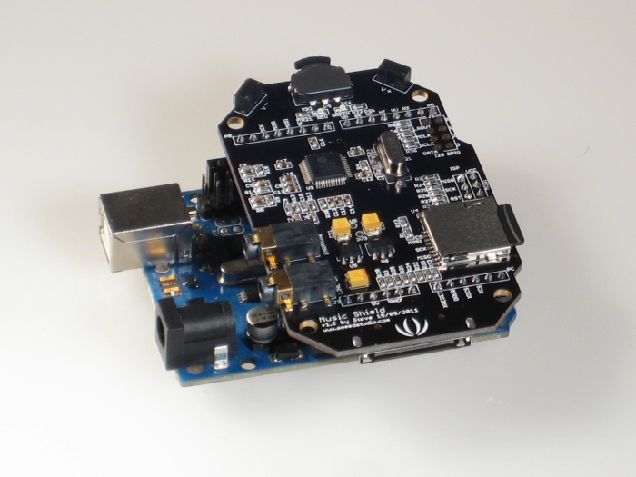
Вставьте в слот microSD-карту объёмом не более 2 Гб и форматом FAT16 либо FAT32 с предварительно записанными на ней трэками. Карты объёмом более 2 Гб или другими файловыми системами не поддерживаются. Продаваемые флэш-карты обычно уже отформатированны в FAT16 или FAT32.
Подлючите наушники или колонки к выходу отмеченному как «Earphone». Рекомендуется использовать динамики с импедансом 16-32 Ом.
Подведите питание и загрузите следующий скетч:
Отлично! Всё работает: кнопки на плате регулируют громкость, переключают трэки, останавливают и запускают воспроизведение; светодиоды отображают текущее состояние.
Программное управление воспроизведением
Предложенный производителем интерфейс не оставляет нам возможности для собственного управления платой. Также плата физически закрывает все контакты на Arduino Uno и большую часть на Arduino Mega.
Эти ограничения можно обойти, если установить между Arduino и Music Shield плату-посредника, к которой в итоге и подключить необходимые компоненты.
Для примера попробуем сами поуправлять некоторыми возможностями платы. Например, с помощью внешней, собственной кнопки будем переключать треки, а с помощью потенциометра управлять громкостью.
Что понадобится
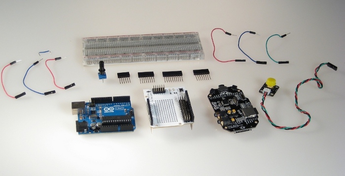
Конструкционное решение
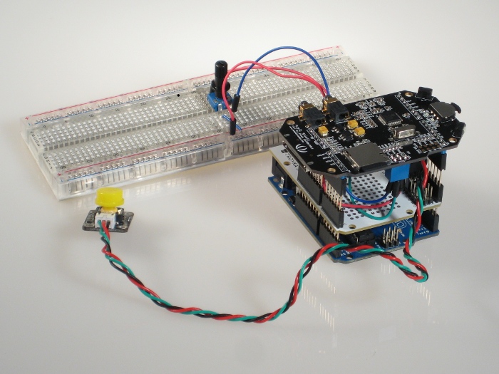
Для получения доступа к контактам Arduino можно воспользоваться платой Troyka Shield. А чтобы подключаемые провода физически пометились между ней и Music Shield стоит увеличить её высоту с помощью контактных колодок. В итоге у нас получится такой бутерброд:
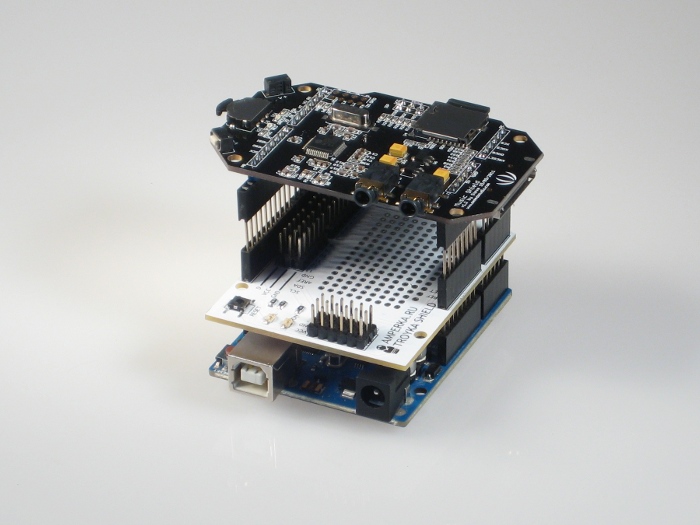
Подключение ICSP
Обратим внимание, что при таком соединении контакты интерфейса ISP/SPI оказались неподключёнными к Ардуино. А они используются Music Shield’ом для коммуникации с чипом-декодером.
Эту проблему можно решить, соединив 11-й, 12-й и 13-й контакты платы с шилдом следующим образом:
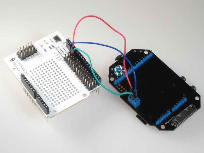
Мы можем так поступить, потому что необходимые нам ICSP-контакты дублируются именно 11-м, 12-м и 13-м контактами. Это справедливо для Arduino Uno и Mega 2560, но не сработает с Leonardo, на которой ISP-header не продублирован обычными контактами.
Итак, наша конструкция стала напоминать бутерброд, однако технически это всё та же самая конструкция, что и в самом начале. Можно убедиться в этом, включив её в сеть.
Доступные и занятые контакты
Перед тем как подключить собственные кнопку и потенциометр, давайте разберёмся, какие из контактов Arduino используются платой Music Shield, а какие не используются. Документация на странице производителя утверждает, что используются цифровые входы со 2-го по 13-й, а аналоговые — с A0 по A3. Также мы знаем, что нулевой и первый цифровые контакты используются для прошивки Arduino, поэтому использовать их для управления по возможности не рекомендуется, хотя и можно.
К счастью, реализованный в библиотеке класс MusicPlayer позволяет легко отключать логику встроенного управления воспроизведением, что позволяет высвободить цифровые входы с третьего по седьмой, которые в штатном режиме заняты кнопками на Music Shield.
Из аналоговых входов нам остаются четвёртый и пятый.
Подключение внешней периферии
Подключим кнопку к четвёртому цифровому входу, а потенциометр — к аналоговому входу A5:
Установим Music Shield поверх Troyka Shield. В итоге должна получиться примерно такая конструкция:
Обзор библиотеки
Класс MusicPlayer , предоставляемый библиотекой позволяет осуществлять все основные функции по управлению плеером:
Посмотреть сигнатуру функций можно в файле MusicPlayer.h , изучить подробней, как они работают — в файле MusicPlayer.cpp .
Информацию об использующихся константах можно также посмотреть в файле MusicPlayer.h .
Реализация программного управления
Теперь можно перейти к написанию скетча, позволяющего управлять громкостью и переключением треков кнопкой и потенциометром.
TobiasVanDyk/VS1053-Micro-Midi-Synthesizer
If nothing happens, download GitHub Desktop and try again.
Launching GitHub Desktop
If nothing happens, download GitHub Desktop and try again.
Launching Xcode
If nothing happens, download Xcode and try again.
Launching Visual Studio Code
Your codespace will open once ready.
There was a problem preparing your codespace, please try again.
Latest commit
Git stats
Files
Failed to load latest commit information.
Readme.md
VS1053 Micro Midi Synthesizer

This is also available as an instructable, and demonstrates the use of the VLSI VS1053b Audio and Midi DSP chip in its real-time Midi mode. In this mode it acts as a 64 voice polyphonic GM (General Midi) Midi synthesizer.
An ATMega328 MCU controls an OLED display, three buttons (Function Select and Up or Down, and passes the Midi data stream through to the audio DSP. The music board chosen was the Adafruit VS1053 codec breakout board, but a Sparkfun music breakout board was also successfully tested. The Adafruit VS1053b libraries were used instead of the much larger SFEMP3 Library (recommended by Sparkfun even though they also have their own set of libraries), because I found the Adafruit code easier to understand.
Most of the code used to control the audio/midi DSP was developed using an Arduino Uno connected to the audio/midi breakout board through a breadboard. After the functions were found to work satisfactory the Uno was used as a programmer for a standalone ATmega 328 which was then put on a small 30×20 size Veroboard together with the 6N139 opto-isolator IC required on the Midi input socket (a 5 pin DIN). Also connected was a small (64×48) OLED shield, three buttons, a Midi activity LED, and a +5 volt barrel connector for power and the audio stereo output connector added. The power requirements are very modest — about 20 mA at 5 volt.
- ATmega328 Micro 28 pin DIP + 28 pin DIP socket
- 6N138 or 6N139 optoisolator + 4 pin DIP socket
- Wemos 64×48 I2C OLED Display or similar
- Adafruit VS1053b Codec breakout board
- 3 miniature pushbuttons
- 5 pin DIN Midi socket PCB mount preferred
- Small LED any colour
- Barrel type power socket for the 5v supply
- Stereo audio socket to connect to an amplifier or headphones
- Resistors: 7 x 10k, 2 x 470 ohm, 2 x 220 ohm
- Capacitors: 0.1uF 50v plastic, 10uf 25v electrolytic, 2 x 27 pF ceramic
- Small pieces of Veroboard (30 strips by 20 columns, and 4 strips by 16 columns), ABS plastic enclosure about 85x55x25mm, wiring and a few screws nuts and washers.
The lid of the enclosure houses the OLED Display, the three buttons that are mounted on another small piece of Veroboard, and the barrel power connector. The main Vero circuit board has two holes to fix the Music breakout board above the ATmega328. For connection details please refer to the Fritzing strip board diagram. The programmed ATmega328 (please refer to the next section for the code) is then inserted into its socket followed by the 6N139 and everything is connected up. The LED is used as a Midi activity indicator and was mounted on the front side of the enclosure. It is connected to the D2 output of the ATmega328 via a 470 ohm resistor. The OLED Display use the 3.3 volt output from the Adafruit board for power — it requires less than 20 mA. Try swapping the two Midi Din connections if you do not hear any audio when you first use the synth.


Details of the sketch that should be uploaded to the ATmega328 is given in MidA.ino. There are seven functions available: Option P: Change Program — change the GM Midi Instrument from 1 to 128 (I used 0 to 127) such as a Piano or Synth sound. Option B: Change the Instrument bank between Melodic (Bank 0) and Percussion (Bank 1). Option V: Adjust the volume from 1 to 10. Option C: Change the Midi channel that the Synth will respond to. The choices are Channel 0, channel 1, channel 9 (percussion), channel 0 and 9, and channel 1 and 9. Option R: Switch the Reverb effect on or off. Option S: Save the current parameters to Eeprom memory (Up) or Read (Down) it back from the Eeprom memory. This is because settings are otherwise not saved when powering down. Option X: Send an all notes off message (Midi Reset).
An eighth option is not yet implemented — this will bypass the ATmega as a Midi filter and connect the output of the optoisolator directly to the Rx pin of the DSP board.
Note that the VS1053b boots in a real-time Midi mode by loading a 1039 byte compressed patch during booting — this also increases the size of the Midi buffer and filters system exclusive Midi data bytes. Details of this patch can be found on the VLSI website.
A slightly modified version of the Adafruit Graphics library had been used to cater for the 64×48 pixel resolution of the OLED Display — please refer to the links given at the end for Mr Mcauser. A list of the required libraries is given in the sketch code.
Importantly when the sketch is executed for the first time on the ATmega328 whether it is on an Uno or standalone, the code will load parameter presets from the ATmega328 Eeprom that may not be valid. In that case you can either write all zeroes to the Eeprom using the X option with the down button, or comment out the line in the void setup function that loads values from the Eeprom when it is first started, adjust your instruments etc. to your liking, and then save your presets with the S option Up button.
Credit is given to all the persons and entities mentioned for their code and libraries..
- VLSI: http://www.vlsi.fi/en/home.html
- Adafruit: https://www.adafruit.com/product/1381
- Github VS1053b: https://github.com/adafruit/Adafruit_VS1053_Library
- Github Graphics: https://github.com/mcauser/Adafruit_SSD1306/tree/esp8266-64×48
- Oled: https://wiki.wemos.cc/products:d1_mini_shields:oled_shield
- Sparkfun: https://www.sparkfun.com/products/12660
About
2017: VS1053 Micro Midi Synthesizer: This uses the VLSI VS1053b Audio and Midi DSP chip in its real-time Midi mode. In this mode it acts as a 64 voice polyphonic GM (General Midi) Midi synthesizer. An Arduino Uno standalone micro controls an OLED display, three buttons (Function Select and Up or Down, and passes the Midi data stream through to t…
AVR Freaks
 GBaars

- 1
- 2
- 3
- 4
- 5
Designing a circuit for the VS1053 in rt MIDI mode
as a synthesizer for an ATXmega256.
The manual mentions, with GPIO0=L and GPIO1=H
after reset the VS1053 is in rt Midi mode.
Then GPIO2 and GPIO3 control earspeaker configuration
but does not mention how (?)
The manual does not mention other connections, how about
the 2 chip-selects and other inputs in rt MIDI mode?
An example circuit diagram for this might help.
- Log in / register to post comments
- 1
- 2
- 3
- 4
- 5
There is a VS1053 shield for Arduino. You can get full code and schematics there. It may take a little effort to tease out the relevant details, but you are more likely with that than folks, here, who would be guessing. And, probably sooner and more accurately!
Until Black Lives Matter, we do not have «All Lives Matter»!
- Log in or register to post comments
- 1
- 2
- 3
- 4
- 5
I haven’t tried, but this project claims to do midi with vs1053:
What «manuals» have you looked at?
Apart from arduino you can also find libs for this thing at adafruit and seeedstudio or google, but the midi part of this chip seems to be less often used.
The vs1053 is also a chip with internal uC / DSP. For some codecs you have to upload a blob with firmware into the device, but I’m not sure if that is needed for midi also.
Bunch of old projects with AVR’s: http://www.hoevendesign.com
- Log in or register to post comments
- 1
- 2
- 3
- 4
- 5
I suggest keep checking eBay for a tone module like this Yamaha MU_5:
Something that is MIDI ready, completely assembled, tested, and ready-to-rock’n’roll for about $60.
I have a GEEtech ? VS1053 board/shield for an Arduino UNO. The pin on the VS1053 that enables the internal MIDI voices is not brought out to the Arduino shield pins. The VS1053 will play MIDI files that have been encoded in format 0. The MIDI voice quality is fair to low compared to used MIDI tone modules. By the way, the eBay prices on these 20-30 year old MIDI tone modules are unbelivable high compared to what they were about ten years ago. They must be very popular.
So, yeah, you can get MIDI ROMpler sounds from the VS1053. But you are probably going to have to be able to actually solder a 30AWG wire-wrap wire directly onto one of the pins of VS1053 IC to do so.
- Log in or register to post comments
GBaars
- 1
- 2
- 3
- 4
- 5
It’s only a hardware matter. In rt midi mode midi commands
are sent to the RxD of the VS1053. The ATxMEGA connects
by UART only. I have bought the VS1053
chip on ebay. The datasheet only mentions to have GPIO0=L
and GPIO=H when reset and GPIO2&3 control ‘earspeaker’
which is sort of ‘spatial-stereo’, not specifying what functions GPIO2&3
have. The Arduino shield is for MP3 player and not for
rt MIDI-mode I presume.
- Log in or register to post comments
- 1
- 2
- 3
- 4
- 5
To maximize EarSpeaker effect, have GPIO2 and GPIO3 set to logic 1 at power-on/reset of the VS1053. These pins are right next to each other and they are at the end of a side on the IC. On my VS1053 Geetech Arduino UNO_shield, these pins are unconnected to anything. So I soldered a wire-wrap wire (AWG30 very thin wire) piece from these two pins on the IC to the Arduino A2 pin. I set A2 to be high, and then toggle the VS1053 reset pin (that is connected to one of the Arduino D-port pins) to enable EarSpeaker. On my VS1053 shield, the GPIO0 and GPIO1 pins have external pull-up resistors, so it is easy to connect them to Arduino A0 and A1. Set the A0 and A1 outputs to 0:1 and toggle the VS1053 reset pin, which is connected to one of the Arduino D-port pins to enter MIDI mode. I had to convert any downloaded MIDI song to MIDI format 0. This is where all the MIDI data for a specific MIDI channel is written sequentially to the MIDI file, and the other MIDI channels come after that data. MIDI files normally use format 1: where the MIDI events for all channels are written to the MIDI file in the order as they are sounded by the synth.
You can use SPI to send MIDI commands to the Real-Time MIDI player in the VS1053. I believe that the VS1053 has 16-bit registers and you put the value 0x00 in the high byte of this 16-bit register. So to send middle C note-ON at medium velocity, first enable the MIDI player with GPIO0 at low and GPIO1 at high at power-up/reset. Then send 0x00: 0x90 on the SPI for Note On channel 1. Follow that with 0x00:0x3C for middle C, and finally 0x00:0x70 for loud velocity. There is also a hardware pin (#26) for UART Rx. Sending MIDI logic at 31250 baud to this pin [the output of the MIDI-IN opto-isolator] with MIDI enabled will play the internal MIDI synth.