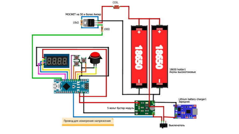
Блок термоконтроля для электронной сигареты на Arduino
Этот устройство предназначено для получения пара с контролем температуры титановой спирали (для никелевой или железной — нужно поменять коэффициент RTCHANGE), что позволяет получать много (или очень много, если фитиль подводит достаточно жидкости) пара без перегрева с образованием разных нехороших веществ, продуктов распада глицерина, пропиленгликоля и ароматизаторов.
Схема предназначена для работы с батареей для RC-моделей, из двух Li-ячеек. Мной был выбран аккумулятор 500 mAh 25C напряжение 7.4V. Ток и нагрузочную способность можно варьировать в широких пределах, лишь бы выдавал достаточный ток с холодной спиралью, когда ее сопротивление минимально.
Теоретически, можно переделать и под аккумулятор с одной ячейкой, но нужно подбирать соответствующие MOSFET-ключи — с низким напряжением переключения и сопротивлением в открытом состоянии. Можно будет даже убрать делители R1+R2 и R3+R4, повысив точность измерения в два раза (хотя реального эффекта будет немного).
Резисторы R5 и R6 — должны быть мощностью не менее 0.25 ватт (а лучше и больше). Выход LED — для пары белых светодиодов, чтобы мог работать как аварийный фонарик.
Аппаратный выключатель отсутствует, но потребляемый ток в спящем режиме — около 1.5 миллиампер, так что неделю можно жить на одной батарее. Кнопку «-» надо завести на D2, нажать не слишком быстро три раза для выхода из спящего режима.
Корпус был напечатан на 3D принтере из PLA. Пустое место под разъемом атомайзера — для проводов батарейки, их на модельных аккумуляторах делают довольно длинными, а обрезать не хотелось.
Arduino Vape Box Mod (With WiFI) 1
In this document, I will explain how I built my own arduino vape box mod. This box will be based on PWM (Pulse Width Modulation). Be aware that the purpose of the document is just to explain how I built my own box. There are many dangers associated with this, so you will want to research the dangers of the components, and apply your own safety features.
This mod uses Lithium batteries which can explode if used improperly, so I would always recommend using protected batteries. In this box, if the batteries are inserted improperly, the results could be disastrous. I’ve taken a few safety precautions on this box, though. You also would want to add safety features in the event that a MOSFET shorts and continuously fires.
In my setup, I can read temperature, humidity, and barometric pressure. In addition, the box will act as my alarm clock, and garage door opener. To use the garage door opener, I’ve built another box which connects to my home wifi. This other box simply closes a relay for one second to simulate pressing the push button. The purpose of this document is simply to give you ideas. You assume all liability if you try to implement this. I’m just documenting the project here for my own reference.
List of Components:
All of these parts were not required just to make the vape box work by itself, but here is what I used:
Arduino IDE installed on your PC
1 x USB Mini cable (to connect PC to Arduino nano)
1 x painted wooden box
4 x Dual 18650 battery sleds
4 x 25A resettable fuses
2 x 3034 MOSFETS (With heatsinks) Beware of fake mosfets!
2 x 15K Resistors
1 x Arduino nano
1 x Screw terminal PCB for Arduino nano
1 x DC-DC Buck Converter (to regulate voltage to 5v)
1 x 1117 voltage regulator (required only to use the wifi card)
1 x ESP8266-01 (Flashed with AT firmware)
1 x DHT22 Temperature and Humidity Sensor
1 x BMP280 (Barometric pressure sensor
(Note — If using a BME 280, I would not have used the DHT22, because the BME will read both temperature and humidity)
1 x ZS-042 Real Time clock module. (For alarm feature) with charging circuit disabled.
1 x CR2032 battery
1 x 510 connector
1 x (20 x 4) LCD Display (with I2C)
2 x Maintained Pushbuttons (For control power and boost power)
2 x Small Momentary Push buttons (to adjust power level)
1 x Large Momentary Push button (Main Vape Button)
1 x Active Buzzer
1 x LED Voltmeter (Mine is rated 0 to 30 volts)
1 x PCB Switch (to turn the wifi card on or off for energy saving)
1 x Atomizer of your choice
8 x 18650 high drain batteries. All of these must be the same capacity, and have the same charge!
3′ of 16 Gauge Wire
2′ of 14 Gauge Wire
7′ Cat 5 cable (I removed all of the conductors to use as the control wiring)
Basic wiring Concepts:
This mod will run a max of 8.4 volts
Power Provision:
All of the individual battery sleds are wired in parallel. This means that all batteries will face the same direction. You must use protection. Don’t rely on yourself putting the batteries in the proper way every time. Use protected batteries. Only connect these batteries if you are familiar with how to safely design your own battery system. Don’t rely on the safety features I’ve provided in this document. Do your own research. You assume all responsibility if you implement this in any way!
Definitions: I’m defining a power pack as a sled of 2 batteries. I’m calling a power bank 2 power packs connected in series (ie. left side and right side) I’m calling the main power unit as both banks (left bank and right bank connected in parallel)
Left Battery bank: The lower left battery pack is connected in series to the upper left battery pack. Fuses are used to protect against reverse polarity, and overcurrent.
Right Battery bank: The lower right battery pack is connected in series to the upper right battery pack. Fuses are used to protect against reverse polarity, and over current.
Using 14 gauge wire, the entire left battery bank is connected in parallel to the entire right battery bank. (providing a total of 8.4 volts when fully charged. Fuses are used to protect against an overcurrent condition.
510 Connector: Using 14 gauge wire, the + side of the main power unit will connect to the center pin of the 510 connector. Using 16 gauge wire, the case of the 510 connector has two 16 gauge wires soldered to the connector. Each of these will go to the Drain (center pin or case) of the 3034 MOSFETS.
Control Power: The + of the main power unit will connect to one side of your maintained Power Switch. Coming out of the power switch, to the + (input) of the DC-DC Buck converter. I’ve used a 5A resettable fuse coming from the + of the main power unit. The – (input) of the Buck Converter will connect to the – of the main power unit. I’ve also jumpered the – of the Input and outputs of the buck converter together to ensure the commons are the same. Warning. If the – potential of the control circuits are at a different potential than the main power unit, the atomizer could fire at will.
If using wifi, we also need to connect the LM1117 voltage regulator to give us a 3.3v supply. The + output of the Buck Converter will connect to the small pcb switch, then from the switch to input of the voltage regulator (right pin) The – output of the buck converter will connect to the – of the voltage regulator (Left pin) and to the – of the ESP8266-01. The VCC (+) of the ESP8266-01 connects to the OUTPUT of the LM1117 (center pin) Daisy chain the + and – from the ESP8266 to the appropriate pins on the BMP280.
Powering all 5v devices: Connect the + and – of the buck converter to the appropriate pins of the DHT22, Arduino nano, LCD Display, and ZS-042 Real Time Clock.
Common Connections: The – of the Buck converter will connect to the remaining Maintained pushbutton (power boost), the small normally open buttons (for up/down power), the main vape button (large normally open button), the – of the voltmeter, and the – of the buzzer.
DHT22: Place a 10K resistor between VCC (left) and Data (2nd Pin). Connect the Data pin of the DHT22 to Digital pin 3 on the arduino.
Button connections: When the buttons are pressed, the following pins will become grounded on the Arduino Nano:
Main Vape Button – Pin 2
Reduce Power Button – Pin 4
Increase Power Button – Pin 5
Power Boost – Pin 11
Then the buzzer (+ side) will be connected to Pin 8
Firing Pin:
Be sure you have a 15K resistor connected across the left and right pins of each 3034 mosfet. This is a very critical connection. The mosfet will not shut off unless this resistor is connected!! Pin 10 of the Nano will connect to the gate (left pin) of both MOSFETs.
I2C Network: Connect pin A5 (SCL) of the arduino nano to the SCL Pins on the LCD Display, BMP280, and ZS-042 module. Pin A4 (SDA) will connect to the SDA Pins on these devices as well. You can just daisy chain from one device to another. If your cabling is long, you might need pullup resistors on these two busses. You can google the pullup resistors if you are having problems. I’m assuming your BMP280 is 5v tolerant for SCL and SCA. If your BMP280 is not 5v tolerant, you can use a logic level converter.
LED Voltmeter: We already have the – connected. On my voltmeter I have 3 leads. Ground… Then a red lead which powers the meter itself, and a yellow lead which measures the battery voltage. I connected the red lead to the + from the Buck converter, and the yellow lead to the + of the main power unit. If your voltmeter only has 2 leads, you can connect one lead to ground, and the other lead to the controlled side of your power switch. This way, the volt meter will not use any current when the power switch is off.
ESP8266: If using this feature, connect the RX of the ESP8266 to TX of the Nano. Connect the TX of the ESP8266 to the RX of the Nano. The CH_PD is connected to VCC to enable the module. I’m assuming the RX is 5v tolerant. If you are worried about damage to the ESP8266 though, you can use a logic level converter, or set up a voltage divider to ensure the RX pin does not receive more than 3.3v.
The Code:
#include <Wire.h>
#include <LiquidCrystal_I2C.h>
#include <SimpleDHT.h>
#include <LowPower.h>
#include “i2c.h”
#include “i2c_BMP280.h”
BMP280 bmp280;
LiquidCrystal_I2C lcd(0x3f,20,4);
//Define the pins
const int ButtonPin = 2;
const int pinDHT22 = 3;
const int DownPowerPin = 4;
const int UpPowerPin = 5;
const int FiringPin = 10;
const int BuzzerPin = 8;
const int PowerBoost = 11;
const int LedPin = 13;
// Discrete Variable Declarations
int ButtonState = 0;
int PowerBoostState = 0;
int BuzzerShutoffOK = 1;
int PowerLevelRaw = 50;
int PowerLevelScaled = 0;
int PowerSetting = 10;
int UpPowerValue = 1;
int DownPowerValue = 1;
// BMP280 Vars
float BMPtemperature;
float BMPpascal;
static float BMPmeters, BMPmetersold;
// Timers
unsigned long ButtonMillisStart = 0;
unsigned long ButtonMillisTimeout = 6000;
unsigned long FlashMillisStart = 0;
unsigned long FlashMillisTimeout = 100;
unsigned long SleepMillisStart = 0;
unsigned long SleepMillisTimeout = 300000;
int ButtonTimeout = 0;
int VapeTime = 0;
int VapeTimeLast = 0;
// Counters
int MyCounter = 0;
int LightCounter = 0;
// One Shots
int ButtonRising = 0;
int ButtonFalling = 0;
int UpPowerONS = 0;
int DownPowerONS = 0;
char LastSecond;
// This is for the Real Time Clock
#define DS3231_I2C_ADDRESS 0x68
// Convert normal decimal numbers to binary coded decimal
byte decToBcd(byte val) <
return( (val/10*16) + (val%10) );
>
// Convert binary coded decimal to normal decimal numbers
byte bcdToDec(byte val) <
return( (val/16*10) + (val%16) );
>
void setup() <
Wire.begin();
Serial.begin(9600);
// onetime-measure:
bmp280.setEnabled(0);
bmp280.triggerMeasurement();
//LCD Setup
lcd.init(); //initialize the lcd
// RTC
// set the initial time here:
// DS3231 seconds, minutes, hours, day, date, month, year
//setDS3231time(30,16,18,7,1,9,2017);
// Setup Pin Modes
pinMode(DownPowerPin, INPUT_PULLUP);
pinMode(UpPowerPin, INPUT_PULLUP);
pinMode(ButtonPin, INPUT_PULLUP);
pinMode(BuzzerPin, OUTPUT);
pinMode(PowerBoost, INPUT_PULLUP);
pinMode(LedPin, OUTPUT);
lcd.noBacklight();
//Configure Wireless
lcd.backlight();
lcd.setCursor(0,1);
lcd.print(“Setting Mode”);
Serial.println(“AT+CWMODE=1”);
delay(1000);
// —————————————
// RTC Logic for Setting clock
// —————————————
void setDS3231time(byte second, byte minute, byte hour, byte dayOfWeek, byte
dayOfMonth, byte month, byte year) <
// sets time and date data to DS3231
Wire.beginTransmission(DS3231_I2C_ADDRESS);
Wire.write(0); // set next input to start at the seconds register
Wire.write(decToBcd(second)); // set seconds
Wire.write(decToBcd(minute)); // set minutes
Wire.write(decToBcd(hour)); // set hours
Wire.write(decToBcd(dayOfWeek)); // set day of week (1=Sunday, 7=Saturday)
Wire.write(decToBcd(dayOfMonth)); // set date (1 to 31)
Wire.write(decToBcd(month)); // set month
Wire.write(decToBcd(year)); // set year (0 to 99)
Wire.endTransmission();
>
void readDS3231time(byte *second,
byte *minute,
byte *hour,
byte *dayOfWeek,
byte *dayOfMonth,
byte *month,
byte *year)
<
Wire.beginTransmission(DS3231_I2C_ADDRESS);
Wire.write(0); // set DS3231 register pointer to 00h
Wire.endTransmission();
Wire.requestFrom(DS3231_I2C_ADDRESS, 7);
// request seven bytes of data from DS3231 starting from register 00h
*second = bcdToDec(Wire.read() & 0x7f);
*minute = bcdToDec(Wire.read());
*hour = bcdToDec(Wire.read() & 0x3f);
*dayOfWeek = bcdToDec(Wire.read());
*dayOfMonth = bcdToDec(Wire.read());
*month = bcdToDec(Wire.read());
*year = bcdToDec(Wire.read());
>
//—————————————-
void loop() <
// read the state of the pushbuttons:
ButtonState = digitalRead(ButtonPin);
PowerBoostState = digitalRead(PowerBoost);
DownPowerValue = digitalRead(DownPowerPin);
UpPowerValue = digitalRead(UpPowerPin);
// Get the BMP280 Data
bmp280.awaitMeasurement();
bmp280.getTemperature(BMPtemperature);
bmp280.getPressure(BMPpascal);
bmp280.getAltitude(BMPmeters);
BMPmetersold = (BMPmetersold * 10 + BMPmeters)/11;
// get the milliseconds for the timers.
unsigned long CurrentMillis = millis();
//Low Power Setup
//attachInterrupt(0, wakeUp, LOW);
if ((CurrentMillis-SleepMillisStart) > SleepMillisTimeout) <
LowPower.powerDown(SLEEP_1S, ADC_OFF, BOD_OFF);
>
// Power Level Control
if (!DownPowerValue) <
if (DownPowerONS==0) <
PowerLevelRaw=PowerLevelRaw-5;
>
DownPowerONS = 1;
if (PowerLevelRaw < 0) <
PowerLevelRaw = 0;
>
>else <
DownPowerONS=0;
>
if (!UpPowerValue) <
if (UpPowerONS==0) <
PowerLevelRaw=PowerLevelRaw+5;
>
UpPowerONS = 1;
if (PowerLevelRaw > 255) <
PowerLevelRaw = 255;
>
>else <
UpPowerONS=0;
>
PowerLevelScaled = PowerLevelRaw/1;
if (!PowerBoostState) <
PowerLevelScaled=PowerLevelScaled*1.3;
>
// ************************* Button is PRESSED *************************
if (ButtonState == LOW) <
SleepMillisStart=CurrentMillis;
ButtonFalling = 0;
// turn on the backlight on lcd
if ((CurrentMillis -FlashMillisStart) < FlashMillisTimeout) <
lcd.backlight();
>else if ((CurrentMillis -FlashMillisStart) < (FlashMillisTimeout *2)) <
lcd.noBacklight();
> else <
FlashMillisStart = CurrentMillis;
>
VapeTime = ((CurrentMillis-ButtonMillisStart) / 1000);
if (VapeTime!=VapeTimeLast) <
lcd.clear();
lcd.setCursor(0,0);
lcd.print(“*** Running ***”);
lcd.setCursor(0,1);
if (PowerBoostState==1) <
lcd.print (“High Power: “);
>else <
lcd.print (“Low Power: “);
>
lcd.print(VapeTime);
VapeTimeLast=VapeTime;
>
if ((CurrentMillis – ButtonMillisStart) < ButtonMillisTimeout) <
digitalWrite(LedPin,HIGH);
analogWrite(FiringPin, PowerLevelScaled);
>else <
ButtonTimeout = 1;
digitalWrite(LedPin,LOW);
digitalWrite(BuzzerPin,HIGH);
analogWrite(FiringPin, 0);
>
ButtonRising = 1;
>else <
// ************************* Button is RELEASED ************************
ButtonRising = 0;
if (LightCounter > 10000)
if (ButtonFalling == 0)
byte second, minute, hour, dayOfWeek, dayOfMonth, month, year;
readDS3231time(&second, &minute, &hour, &dayOfWeek, &dayOfMonth, &month,
&year);
if (second!=LastSecond) <
LightCounter++;
float temperature = 0;
float humidity = 0;
int err = SimpleDHTErrSuccess;
if ((err = dht22.read2(pinDHT22, &temperature, &humidity, NULL)) != SimpleDHTErrSuccess) <
//Serial.print(“Read DHT22 failed, err=”); Serial.println(err);delay(200);
return;
>
//lcd.backlight();
if (LightCounter > 300) <
lcd.noBacklight();
>else <
lcd.backlight();
>
//lcd.clear();
lcd.setCursor(0,0);
lcd.print(hour);
lcd.print(“:”);
if (minute < 10)
lcd.print(minute);
lcd.print(“:”);
if (second < 10)
lcd.print(second);
lcd.print (” “);
temperature=temperature*1.8+32;
lcd.print(temperature);
lcd.print((char)223);
lcd.print (“F “);
LastSecond = second;
lcd.setCursor(0,2);
lcd.print(“PSR: “);
lcd.print(BMPpascal/3386.38867);
lcd.print(” In Hg “);
lcd.setCursor(0,3);
lcd.print(“Raw Power: “);
lcd.print(PowerLevelScaled);
lcd.print(” “);
>
ButtonTimeout = 0;
ButtonMillisStart = CurrentMillis;
if (BuzzerShutoffOK == 1) <
digitalWrite(BuzzerPin,LOW);
>
digitalWrite(LedPin,LOW);
analogWrite(FiringPin, 0);
// Alarm Logic
byte second, minute, hour, dayOfWeek, dayOfMonth, month, year;
readDS3231time(&second, &minute, &hour, &dayOfWeek, &dayOfMonth, &month,
&year);
if ((hour==5) and (minute==0)) <
//Serial.println(“Alarm”);
BuzzerShutoffOK=0;
digitalWrite(BuzzerPin,HIGH);
>else <
BuzzerShutoffOK=1;
>
if (!UpPowerValue and !DownPowerValue and !PowerBoostState) <
analogWrite(FiringPin, 0);
lcd.clear();
lcd.setCursor(0,0);
lcd.print(“Opening Garage Door”);
lcd.setCursor(0,1);
lcd.setCursor(0,1);
lcd.print(“Setting Length… “);
Serial.println(“AT+CIPSEND=20”);
delay(1000);
lcd.setCursor(0,1);
lcd.print(“Closing Connection “);
Serial.println(“AT+CIPCLOSE”);
delay(1000);
Upload your project:
Remove the nano from your project, and connect it to your PC. Verify the code above, and install any libraries with you are missing.
Locate this line in your code: //setDS3231time(30,16,18,7,1,9,2017); Remove the “//” and set the clock a minute fast. This string is i the format: seconds, minutes, hours, day, date, month, year.
10 seconds before the set time is reached, press the upload button in your arduino IDE. Verify that “upload complete” is displayed roughly when the set time is at the actual time of day. Now, comment out this same line using “//” before the setDS3231 time function, and upload again. This will ensure the time is not reset every time you power the arduino.
Testing your project
Check for any shorts with your multimeter. Check continuity of all connections to ensure you have no broken wires.
Turn the voltage regulator down to zero.
Be sure to insert the batteries correctly. You can test this with just two batteries in series with each other on either side.
Using a voltmeter turn the buck converter up until you have 5volts.
With no atomizer attached, ensure that all of your circuitry is working properly. The back of the LCD display has a contrast display that you will need to adjust. Hold the firing button in for at least 6 seconds. The buzzer should sound.
Go outside the house to an open area, and place your atomizer into the 510 connector. Take care to have the ability to remove it quickly if it starts to fire immediately.
Again… Be ready to remove the atomizer or batteries immediately in case something goes wrong, and test fire the atomizer. The default power is around 20%. You may need to increase or decrease the power level using your power buttons, or power boost button. The display will read RAW POWER on a scale of 0 to 255…. 255 being 100%.
If everything works well, you are in good shape! Be sure to always remove the batteries when unattended. By default, the alarm will sound at 5am each morning. To change this, just adjust this line of code:
if ((hour==5) and (minute==0))<
Again — You assume all liability if you try to implement this. I’m just documenting the project here for my own reference.
Hints for your garage door opener: You can use another ESP8266 in your garage using EasyESP firmware. An output on the ESP8266 can be connected to a transistor controlled relay, which simulates pressing the pushbutton. You will need to adjust the IP address in the vape code, and the command you are sending to activate the relay. Some additional code might be required to to shut off the relay one second later.
In my case, I just had an arduino uno board with an Ethernet shield, and programmed it as a web server to turn on the relay for once second when it receives the proper GET command.
Saved searches
Use saved searches to filter your results more quickly
You signed in with another tab or window. Reload to refresh your session. You signed out in another tab or window. Reload to refresh your session. You switched accounts on another tab or window. Reload to refresh your session.
Вейп Боксмод на Ардуино
License
AlexGyver/GyverMOD
Name already in use
- Local
- Codespaces
Use Git or checkout with SVN using the web URL.
Work fast with our official CLI. Learn more about the CLI.
Sign In Required
Please sign in to use Codespaces.
Launching GitHub Desktop
If nothing happens, download GitHub Desktop and try again.
Launching GitHub Desktop
If nothing happens, download GitHub Desktop and try again.
Launching Xcode
If nothing happens, download Xcode and try again.
Launching Visual Studio Code
Your codespace will open once ready.
There was a problem preparing your codespace, please try again.
Latest commit
Git stats
Files
Failed to load latest commit information.
README.md
Вейп БоксМод GyverMOD
GyverMOD_libs — папка с файлами библиотек, установить в C:\Program Files\Arduino\libraries
GyverMOD_v._1.0.*_DISP — прошивка для Ардуино, актуальная версия с варивольтом
GyverMOD_v._1.2.*_DISP — прошивка для Ардуино, актуальная версия с варивольтом и ручным вариваттом
images — рендеры 3D модели, компоновка
ВНИМАНИЕ! ПУТЬ К ПАПКЕ СО СКЕТЧЕМ НЕ ДОЛЖЕН СОДЕРЖАТЬ РУССКИХ СИМВОЛОВ! ВО ИЗБЕЖАНИЕ ПРОБЛЕМ ПОЛОЖИТЕ ПАПКУ В КОРЕНЬ ДИСКА С.
Как сделать вайп на ардуино
If nothing happens, download GitHub Desktop and try again.
Launching GitHub Desktop
If nothing happens, download GitHub Desktop and try again.
Launching Xcode
If nothing happens, download Xcode and try again.
Launching Visual Studio Code
Your codespace will open once ready.
There was a problem preparing your codespace, please try again.
Latest commit
Git stats
Files
Failed to load latest commit information.
README.md
Вейп БоксМод GyverMOD
GyverMOD_libs — папка с файлами библиотек, установить в C:\Program Files\Arduino\libraries
GyverMOD_v._1.0.*_DISP — прошивка для Ардуино, актуальная версия с варивольтом
GyverMOD_v._1.2.*_DISP — прошивка для Ардуино, актуальная версия с варивольтом и ручным вариваттом
images — рендеры 3D модели, компоновка
ВНИМАНИЕ! ПУТЬ К ПАПКЕ СО СКЕТЧЕМ НЕ ДОЛЖЕН СОДЕРЖАТЬ РУССКИХ СИМВОЛОВ! ВО ИЗБЕЖАНИЕ ПРОБЛЕМ ПОЛОЖИТЕ ПАПКУ В КОРЕНЬ ДИСКА С.
GyverMOD – вейп боксмод своими руками на Arduino
ВОЗМОЖНОСТИ
Варивольт, транзистор управляется при помощи ШИМ сигнала. Измерение и отображение напряжения на аккумуляторе с точностью до 0.02 Вольта. Отсечка по минимальному напряжению (защита от переразряда). При разряженном аккумуляторе на дисплей будет выведено – – – 0. Турбо режим парения (мосфет тупо открывает напряжение с акумов на койл).
НАСТРОЙКИ
В самом начале кода можно включить/выключить приветственную надпись, а также отображение заряда аккумулятора при старте системы.
КНОПКИ
При удержании средней кнопки отображается текущее напряжение на аккумуляторе.
Верхняя и нижняя кнопки служат для настройки текущего режима (увеличить/уменьшить цифру).
Кнопка парения (Fire), при нажатии и удержании подаёт напряжение на койл согласно выбранному режиму. При двойном нажатии и удержании – турбо режим, “прожечь” койл.
РЕЖИМ ВАРИВОЛЬТ
Есть только режим варивольт, кнопками ВВЕРХ и ВНИЗ регулируется напряжение на койле. Напряжение ограничено сверху текущим зарядом аккумулятора (то есть на койл нельзя подать больше, чем сейчас на аккумуляторе. НУ это как минимум логично)..
GyverMOD v2
ВОЗМОЖНОСТИ
Варивольт, вариватт, ручной ввод сопротивления, транзистор управляется при помощи ШИМ сигнала. Измерение и отображение напряжения на аккумуляторе с точностью до 0.02 Вольта. Отсечка по минимальному напряжению (защита от переразряда). При разряженном аккумуляторе на дисплей будет выведено – – – 0. Турбо режим, уход в режим сверхнизкого энергопотребления, 5 нажатий для вывода из сна, 3 нажатия для ввода в сон, автоотключение
НАСТРОЙКИ
В самом начале кода можно включить/выключить/настроить
• калибровка вольтметра
• приветствие (слова GYVER VAPE при включении)
• отображение напряжения аккумулятора при запуске
• таймер сна в секундах
• отсечка затяжки, в секундах
• турбо режим
• отображать заряд в процентах
• нижний порог срабатывания защиты от переразрядки аккумулятора, в Вольтах
КНОПКИ
При удержании кнопки РЕЖИМ отображается текущее напряжение на аккумуляторе, в вольтах или процентах.
Кнопки ВВЕРХ И ВНИЗ служат для настройки текущего режима (увеличить/уменьшить цифру).
Кнопка ПАРИТЬ, при нажатии и удержании подаёт напряжение на койл согласно выбранному режиму. При двойном нажатии и удержании – турбо режим, “прожечь” койл. При тройном нажатии мод переводится в режим сна. Чтобы выйти из режима сна, нужно 5 раз нажать на кнопку ПАРИТЬ. Причём пятый раз можно удерживать, сразу будет подан ток на койл согласно последнему выбранному режиму. При каждом нажатии появляется буква слова VAPE, на 5 нажатий у вас есть 3 секунды, иначе мод снова вернётся в режим сна.
РЕЖИМ ВАРИВОЛЬТ
Кнопками ВВЕРХ и ВНИЗ регулируется напряжение на койле. Напряжение ограничено сверху текущим зарядом аккумулятора (то есть на койл нельзя подать больше, чем сейчас на аккумуляторе. НУ это как минимум логично).
РЕЖИМ ВАРИВАТТ
Кнопками ВВЕРХ и ВНИЗ регулируется расчётная мощность на койле. Мощность ограничена сверху текущим зарядом аккумулятора, а также текущим настроенным сопротивлением койла.
РЕЖИМ ВВОДА СОПРОТИВЛЕНИЯ
Кнопками ВВЕРХ и ВНИЗ задаётся сопротивление койла. Ограничено сверху 3 Омами, просто чтобы было.
БоксМод своими руками под управлением Arduino

позавчера посмотрел видео, круто) реально здорово) а у китайских за ту же цену функции те же? или самоделка лучше?
Помимо вариватта сделай режим термоконтроля и зарядку/прошивку от одного порта. И можно в серию пускать
«По требованию владельца это видео не воспроизводится на других сайтах» опять музыка?
Посмотрел видос, стало интересно.
Есть несколько вопросов, а именно:
1. Какой минимальный порог сопротивления спирали оно ест? Я так понимаю можно использовать сабомные намотки ибо это все равно бокс на мосфете, только с контролем зарядки\разрядки и шим контроллером?
2. Еще интересует момент зарядки аккумов, может я был невнимателен, но одной платой зарядки заряжаются два акка без балансировки? Мне казалось, что это не есть гуд.
3. Какая кнопочка используется под Fire?
4. Ардуино сама может посчитать сопротивление спирали? Ведь в таком случае вариватт по простой формуле P = U 2/ R осуществляется, не? Или только считывать данные с омметра?
Если где то не прав или ошибся прошу поправить.
@alexgyver, тоже вопрос не по теме: какова максимальная частота аналогового сигнала для Ардуино?
а в чём хохма с вазелином?
@AlexGyver, вопрос немного не по видео, но возможно ли запилить какую-нибудь коробочку на Ардуинке, позволяющую искажать аудиосигнал?
К примеру «эхо», reverb, pitch и т.п.
и ни одной шутки про геев, куда катится мир?

Ответ на пост «Мой способ бросить курить. (правило пяти минут)»
А вот мой действительно лёгкий способ бросить курить или парить вейп!
Я сам курил с 12 до 30 лет и бросил таким способом совершенно без страданий, регистрации и смс. А также пара моих друзей повторили мой путь.
Весь путь займет у вас около 1 месяца и порядка 3-4 тысяч рублей.
Для меня всегда главной проблемой была никотиновая зависимость. Вот эта "ломка" — две недели, когда тебя все бесит, давление скачет, суставы выкручивает, постоянное чувство голода.
Итак, во первых, для начала нужно перейти на вейп. Да-да, там ещё больше никотина и зависимость развивается ещё сильнее. Но это временный этап. Для начала вы отвыкнете от запаха сигарет (он очень быстро начнет вас бесить) и сломаете привычку регулярно бегать на улицу и другие ритуалы связанные именно с курением.
Дальше нам останется снизить физическую зависимость от никотина. Для этого нужен любой, можно самый простейший дешёвый вейп, позволяющий заливать в него жидкость, 1 банку с никотиновой жидкостью и 2-3 без никотина.
Спокойно и без зазрений совести выкуриваем первые полбанки с никотином. Когда банка наполовину опустела — доливаем туда жидкость без никотина. Вот ваша дозировка снизилась уже в два раза. Когда останется снова полбанки — доливаете снова жидкость без никотина. И так до бесконечности, пока содержание никотина в выпариваемой вами жидкости не будет стремиться к нулю.
Такое плавное снижение дозы никотина позволит вам практически незаметно для организма снять физическую тягу к никотину, а для заглушения психологической привычки у вас всегда есть возможность немножко "покурить".
Через пару-тройку недель вы обнаружите, что организм отвык и вы можете просто забыть дома ваш вейп, не парить несколько часов и не испытывать дискомфорта.
Это значит, что вы восхитительны, вы смогли победить никотиновую зависимость и останется только выкинуть этот несчастный вейп и наслаждаться чистыми лёгкими.