How To Configure and Pair Two HC-05 Bluetooth Modules as Master and Slave | AT Commands
In this Arduino Tutorial we will learn how to configure and pair two HC-05 Bluetooth Modules as Master and Slave devices.You can watch the following video or read the written tutorial below.
Overview
In my previous two tutorials we already learned how to connect the HC-05 Bluetooth Module to the Arduino and make a communication between an Android smartphone and the Arduino. In those tutorials we used the HC-05 Bluetooth module with its default configuration, as a slave device.
Configuring the HC-05 Bluetooth Module – AT Commands
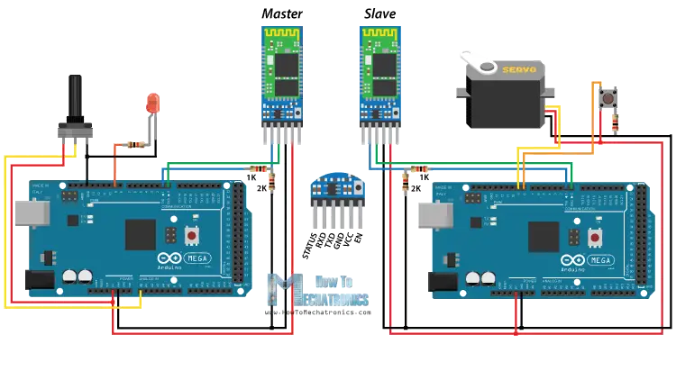
For this tutorial we need to configure both modules. In order to do that we need to switch to AT Command Mode and here’s how we will do that. First we need connect the Bluetooth module to the Arduino as the circuit schematics explained in the previous tutorials. What we need to do additionally is to connect the “EN” pin of the Bluetooth module to 5 volts and also switch the TX and RX pins at the Arduino Board.
So the RX pin of the Arduino needs to be connected to the RX pin of the Bluetooth module, through the voltage divider, and the TX pin of the Arduino to the TX pin of the Bluetooth module. Now while holding the small button over the “EN” pin we need to power the module and that’s how we will enter the command mode. If the Bluetooth module led is flashing every 2 seconds that means that we have successfully entered in the AT command mode.
After this we need to upload an empty sketch to the Arduino but don’t forget to disconnect the RX and TX lines while uploading. Then we need to run the Serial Monitor and there select “Both NL and CR”, as well as, “38400 baud” rate which is the default baud rate of the Bluetooth module. Now we are ready to send commands and their format is as following.
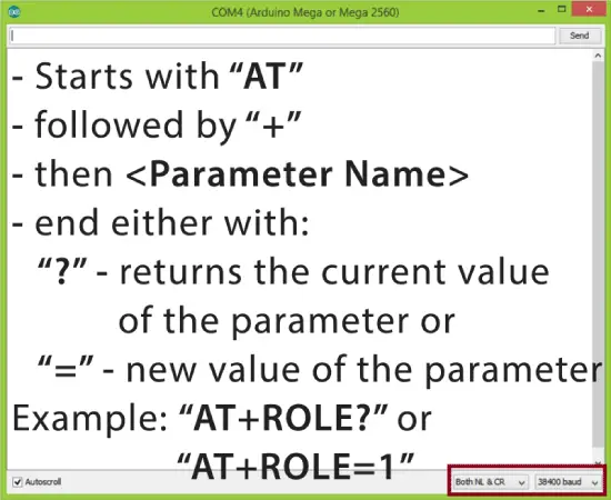
All commands start with “AT”, followed by the “+” sign, then a <Parameter Name> and they end either with the “?” sign which returns the current value of the parameter or the “=” sign when we want to enter a new value for that parameter.
Slave Configuration
So for example, if we type just “AT” which is a test command we should get back the message “OK”. Then if we type “AT+UART?” we should get back the massage that shows the default baud rate which is 38400. Then if we type “AT+ROLE?” we will get back a massage “+ROLE=0” which means that the Bluetooth device is in slave mode. If we type “AT+ADDR?” we will get back the address of the Bluetooth module and it should looks something like this: 98d3:34:905d3f.
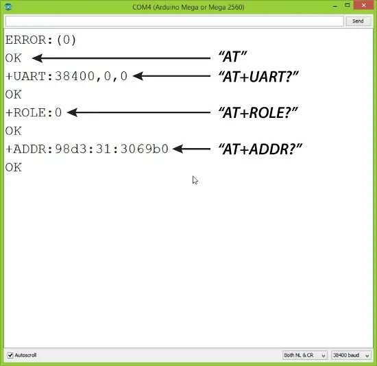
Now we need to write down this address as we will need it when configuring the master device. Actually that’s all we need when configuring the slave device, to get its address, although we can change many different parameters like its name, baud rate, pairing password and so on, but we won’t do that for this example.
Master Configuration
Ok now let’s move on and configure the other Bluetooth module as a master device. First we will check the baud rate to make sure it’s the same 38400 as the slave device. Then by typing “AT+ROLE=1” we will set the Bluetooth module as a master device. After this using the “AT+CMODE=0” we will set the connect mode to “fixed address” and using the “AT+BIND=” command we will set the address of the slave device that we previously wrote down.
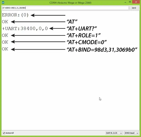
Note here that when writing the address we need to use commas instead of colons. Also note that we could have skipped the previous step if we entered “1” instead of “0” at the “AT+CMODE” command, which makes the master to connect to any device in its transmission range but that’s less secure configuration. Here you can find a complete list of commands and parameters: HC-05 AT Commands List
Nevertheless, that’s all we need for a basic configuration of the Bluetooth modules to work as a master and slave devices and now if we reconnect them in normal, data mode, and re-power the modules, in a matter of seconds the master will connect to the slave. Both modules will start flashing every 2 seconds indicating a successful connection.
Communication Between Two HC-05 Bluetooth Module Example
Ok so now we are ready make the practical example for this tutorial. Here’s the circuit schematics. We will use a potentiometer, at the master, to control a servo motor at the slave. And vice versa, we will use a push button, at the slave, to control a LED at the master.
You can get the components needed for this Arduino tutorial from any of the sites below:
- HC-05 Bluetooth Module ……………. Amazon / Banggood / AliExpress
- Arduino Board …………………………… Amazon / Banggood / AliExpress
- Servo Motor…………………………….…. Amazon / Banggood / AliExpress
- Potentiometer……………..………..……. Amazon / Banggood / AliExpress
- 3x 220 Ohms resistors………………… Amazon / Banggood / AliExpress
- Breadboard and Jump Wires ………. Amazon / Banggood / AliExpress
Disclosure: These are affiliate links. As an Amazon Associate I earn from qualifying purchases.
Arduino Source Codes
Description: So first we need to define the pins and some variables needed for the program. In the setup section, at the master, we set the LED pin as output and set it low right away, as well as, start the serial communication at 38400 baud rate. Similar, at the slave, we set the button pin as input, define the servo to which pin is connected and start the serial communication with the same baud rate.
In the loop section, in both code, with the Serial.available() function we will check whether there is available data in the serial port to be read and using the Serial.read() function we will read and store the data into the “state” variable. So if the master receive the character ‘1’ which is sent from the slave when the button state is high, or the button is pressed, the LED will be on. Else if the character is ‘0’ the LED will be off.
As for the servo motor control, first at the master, we read the potentiometer value and map it into a suitable range for the servo from 0 to 255. This value is sent to the slave which use it to rotate the servo motor accordingly. That’s all we need and here’s the demonstration of the example.
Master Code:
Slave Code:
That’s all and if you have any problems, feel free to ask for help in the comments section below.
Arduino.ru
Я приобрел две ардуино и два блютуз модуля HC-06.
Я хочу сделать так называемую Метео станцию на двух ардуино по блютузу.
Суть в том чтобы с одной ардуино освещение и температуру с улицы передавало на другую ардуино по блютузу.
Освещение для лампы ( если темно включается, а если светло то выключается, также будет кнопка для вкл. и выкл. ) . Если на улице поменялась температура, то отправляется на основную ардуино, и потом при подключении телефона оно показывало температуру. Т.е. в основной ардуино температура оставалось в памяти.
Как связать 2 блютуз модуля ардуино
Для настройки Bluetooth модулей HC-05 загрузите этот скетч на плату.
//Начало скетча Копировать этот код
После загрузки скетча соберите все, как показано на этой схеме.
И следуйте инструкциям на видео, которое я оставил в конце этой статьи.
Ниже представлены два скетча для взаимодействия двух плат Arduino с применение Bluetooth модулей HC-05.
Скетч для платы Arduino Nano (с кнопкой)
//Начало скетча Копировать этот код
Скетч для платы Arduino Uno которая будет включать светодиод
//Начало скетча Копировать этот код
После загрузки скетчей соберите все, как показано на этой схеме.
Если все верно, то подключаем питание и проверяем нажатием кнопки. Более подробно, смотрите видео, которое ниже.
Подробное видео по настройке Bluetooth модуля HC-05 при помощи AT команд.
Творческая мастерская Мастер Колотушкин 2023
Проекты на базе Arduino для начинающих, электронные самоделки своими руками.
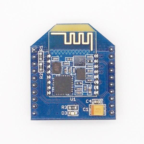
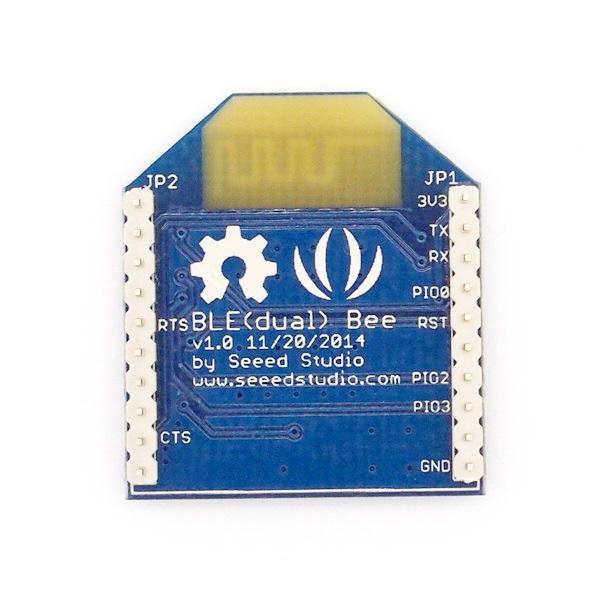
BLE (dual) Bee v1.0
BLE (dual) Bee v1.0 uses CSR dual mode Bluetooth chip,with the ARM architecture single chip which supports AT instructions, Users can develop flexibly according to the serial baud rate, equipment name, pairing password.
Features
BT Version: Bluetooth Specification V4.0 & BLE
UART send and receive max bytes is 512
Other device to module in SPP mode: 90 Bytes per packet
Other device to module in BLE mode: 20 Bytes per packet
Two data transmission mode, balance mode and high speed mode
Working frequency: 2.4GHz ISM band
Modulation method: GFSK(Gaussian Frequency Shift Keying)
RF Power: -23dbm, -6dbm, 0dbm, 6dbm.
Speed: Asynchronous: 3K Bytes
Synchronous: 3K Bytes
Security: Authentication and encryption
Service: Slave SPP, Peripheral BLE, UUID FFE0,FFE1
Power: +3.3VDC 50mA
Long range: SPP 30 meters, BLE 60 meters
Power: SPP 13.5mA, BLE 9.5mA
Working temperature:–5
Specification
U1:U1 is the wireless module,It includes automatic power on reset circuit.
D3:The led display two work models: sleeping whit It slowly flashing;connected status whit It continuously lighting.
JP1&JP3:The standard Bee connector.
Cautions
The supply voltage of this module is 2.5V
3.7V, higher than this may cause permanent damage to the device.BLE transmission speed is slower than SPP transmission, so we selected the lower one in the design, in accordance with the speed of a BLE dual-mode product planning.
Hardware Installation
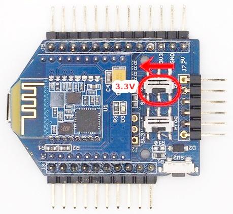
Connecting Bluetooth to PC through Uart Bee
The Bluetooth provides a standard XBee socket. In here we use a UartSBee V5 to connect Bluetooth and PC, ensure the supply voltage was selected as 3.3V by slider.
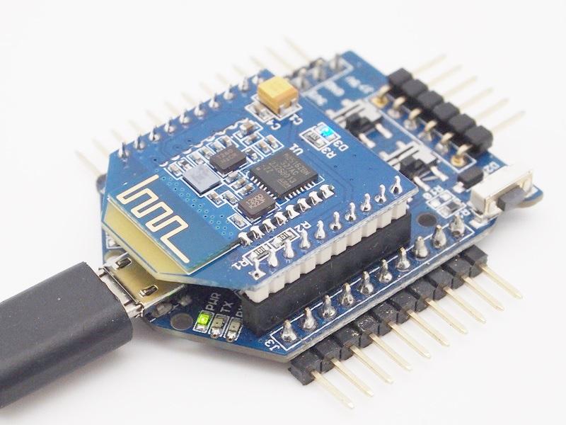
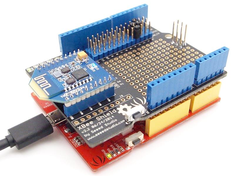
Connecting Bluetooth to Arduino
Here we use XBee Shield as a bridge between Bluetooth and Seeeduino Lotus.
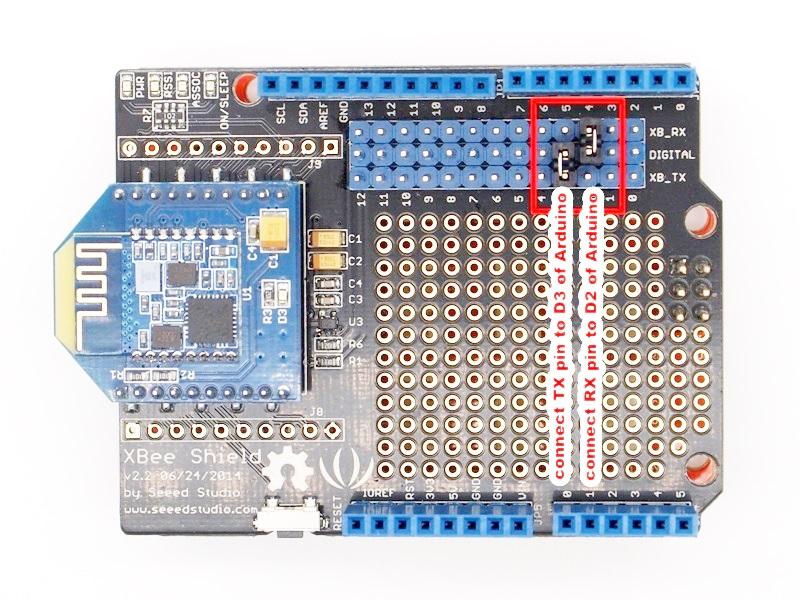
Since the hardware UART of Seeedino was used as debug with PC, We choose D2 and D3 to simulate software UART to communicate with Bluetooth. please refer to the jumper setting on below picture
Software Instruction
Conventions
- In EDR mode, only slave can be configured while either master or slave can be in BLE mode.
- Factory default setting:
- EDR Name HMSoft, Slave role, PinCode 1234
- BLE Name HMSoft, Slave role, PinCode 000000
- Baud: 115200, N, 8, 1;
- Uppercase AT command format. string format, without any other symbol. (e.g. \r or \n).
- Any incorrect command would be no response.
AT Commands
1. Test Command
Send Receive Parameter AT OK/ER/Disconnect link None If module is not connected to remote device will receive: “OK”
If module has an error, will receive: “ER”
If Module has connected, module will disconnected from remote device, if “AT + NOTI” is setup to 1, will receive information string
2. Query module EDR addressSend Receive Parameter AT+ADDE? OK+ Get: MAC None 3. Query module BLE address
Send Receive Parameter AT+ADDB? OK+ Get: MAC None 4. Query/Set Authentication mode
0 – Not authentication
1 – Must authenticationAT+AUTH0: allow made an insecure connection.
AT+AUTH1: every connection must with authentication.
5. Query/Set A to B mode0 – Not Open ATOB
1 – Open ATOB modeThis command must work with AT+MODE0 command. When A device (SPP mode) connect to the module and B device (BLE mode) is also connect to the module, The data string from A device send to the module will send to B device. The data string from B device send to the module is also send to the A device.
6. Query/Set baud rate1 — 4800
2 – 9600
3 – 19200
4 – 38400
5 – 57600
6 – 115200
7 — 2304007. Clear bond information
Send Receive Parameter AT+BONDE OK+BONDE Clear EDR bond info AT+BONDB OK+BONDB Clear BLE bond info BLE mode not supports it yet.
8. Clear Last Connected EDR Device AddressSend Receive Parameter AT+CLEAE OK+CLEAE None 9. Clear Last Connected BLE Device Address
Send Receive Parameter AT+CLEAB OK+CLEAB None 10. Query/Set Module DUAL Work Mode
0 – Allow dual connect.
1 – Allow one connect.AT+DUAL0: allow two connections at same time (SPP and BLE).
AT+DUAL1: Only allow one connection at same time (SPP or BLE)
11. Query/Set hardware flow control switch0: Hardware flow control off
1: Hardware flow control on12. Query/Set module data transmission speed mode
0: Balance mode
1: High speed modeIn balance mode, we balanced SPP and BLE with a steady speed.
In high speed mode, we don’t control speed, so SPP mode will got high speed.
In high speed mode, module lost RESETB pin function, but you still could use
“AT+RESET” command to reset module.
13. System Help InformationSend Receive Parameter AT+HELP? Help Information None 14. Query/Set module loaded notify
0: Loaded notify 0ff
1: Loaded notify onWhen “AT+INIT1” is setup, after module loaded, module will output “OK+INIT” string through UART.
15. Query/Set Module Work Mode0 – Data transmission.
1 – Remote control.AT+MODE0: Only transfer data when connection establishment.
AT+MODE1: Transfer data and response AT commands.
16. Query/Set Notify information0: Don’t Notify
1: NotifyAfter AT+NOTI1, module will send connect or disconnect string through
UART when module state is change:
OK+CONE ======== EDR connect
OK+LSTE ========= EDR disconnect
OK+CONB========= BLE connect
OK+LSTB ========= BLE disconnect
OK+LSTA ========= except disconnect, module will reset after 500 ms.
17. Query/Set notify mode0: without address
1: with addressThis command must work with “AT+NOTI1”, if this switch is open, when the module connect to disconnect, the prompt string will include the remote address.
18. Query/Set Module EDR nameMax length is 12.
Default: HMSoft19. Query/Set Module BLE name
Max length is 12.
Default: HMSoft20. Query/Set PIO1 output status (System LED)e
0: Unconnected Output 500ms High 500ms Low, Connected output High.
1: Unconnected output Low, Connected output High.
Default: 021. Query/Set PIO output status
3 (HM-13)
0: Output Low
1: Output High
?: Query22. Query/Set EDR Pin Code
Max length: 6
Default: 123423. Query/Set BLE Pin Code
999999
Default: 00000024. Query/Set UART parity bit
0: Parity None
1: Parity even
2: Parity odd25. Restore all setup value to factory setup
Send Receive Parameter AT+RENEW OK+RENEW None 26. Restart module
Send Receive Parameter AT+RESET OK+RESET None 27. Query BLE RSSI value
9999: No connection
9998: Try later
9997: Read error
Xxxx: RSSI valueThis command must use after “AT+MODE1” is setup. This command is only used by remote Bluetooth device. 28. Query EDR RSSI value
9999: No connection
9998: Try later
9997: Read error
Xxxx: RSSI value29. Query Last Connected EDR Device Address
Send Receive Parameter AT+RADE? OK+Get:MAC Address None 30. Query Last Connected BLE Device Address
Send Receive Parameter AT+RADB? OK+Get:MAC Address None 31. Query/Set Master and Slaver Role
0: Peripheral
1: CentralThis command will take effect after module next power on or reset. 32. Query/Set EDR work mode
0: Discovery and connectable
1: Only connectable33. Query/Set UART stop bit
0: 1 stop bit
1: 2 stop bits34. Query Software Version
Programming
Configure the Bluetooth module with Serial under Windows
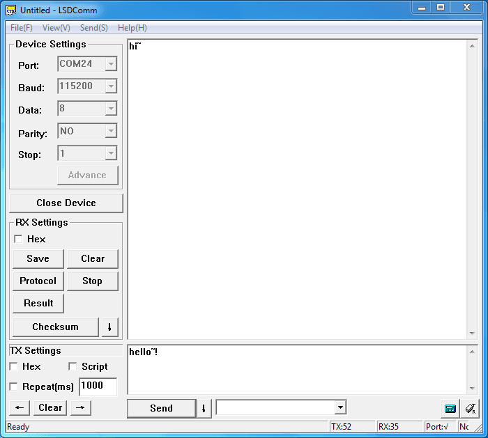
This section shows how to configure Bluetooth with PC, some basic methods of setting could be learn. Set up hardware connection refer to “Hardware Installation” section. You will find the blue LED on the module flashes illustrate no connection is set up.
Open a serial terminal and set Baud Rate:115200, Databits: 8, Stopbits: 1 and No Flow Control. Send “AT” to Bluetooth with the serial terminal and “OK” will be return if all goes well. The Bluetooth only respond AT commands when no connection was set up, or all commands were seen as string and sent out. You can distinguish the status through LED indicates.
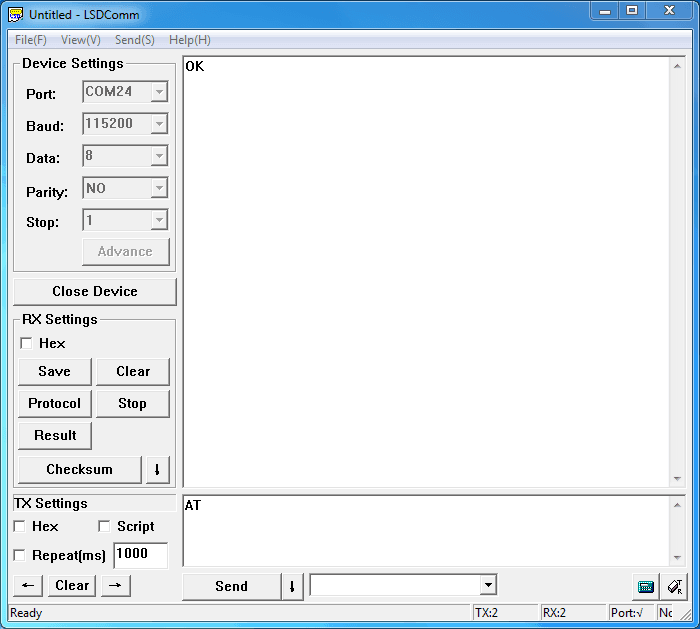
Then some useful configurations could be sent. Here’s are some samples of commands and response.
1. Test serial connection, send “AT”, will return “OK”.
2. Restore factory settings, send “AT+RENEW”, return “OK+RENEW”.
3. Reset baud rate of serial port, send “AT+BAUD2”, return “OK+Set:2”.
4. Enable authentication, send “AT+AUTH1”, return “OK+Set:1”.
5. Reset the Bluetooth, send “AT+RESET”, return ”OK+RESET”.
6. Query firmware version, send “AT+VERS?”, return “OK+Get:HMSoftV217”.
7. Query MAC of EDR, send “AT+ADDE?”, return “OK+Get:000E0E002074”.
8. Query MAC of BLE, send “AT+ADDB?”, return “OK+Get:000E0B002074”.
9. Set the name of EDR, send “AT+NAMEHM-13-EDR”, return “OK+Set:HM-13-EDR”.
10. Set the name of BLE, send “AT+NAMEHM-13-BLE”, return “OK+Set:HM-13-BLE”.
11. Set the password of EDR, send “AT+PINE123451”, return “OK+Set:123451”.
12. Set the password of BLE, send “AT+PINB123451”, return “OK+Set:123451”.
13. Enable discovery and connectable, send “AT+SCAN0”, return “OK+Set:0”.
14. Enable notify information of connection, send “AT+NOTI1”, return “OK+Set:1”.
15. Notify information include address, send “AT+NOTP1”, return “OK+Set:1”.
16. Enable user key, send “AT+PIO01”, return “OK+Set:1”.
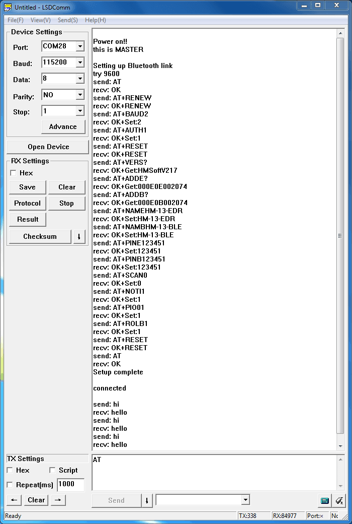
17. Set to Central mode, send “AT+ROLB1”, return “AT+ROLB1”.
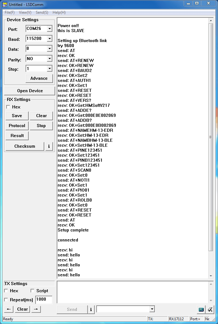
Or Set to Peripheral mode, send “AT+ROLB0”, return “AT+ROLB0”.We use two Bluetooth connected with PC, one was set as Central while the other is Peripheral. Several seconds later they find each other and the LED stop flash, connected!
Communicate with iPhone
This kind of Bluetooth module has two protocol: Bluetooth EDR(Enhanced Data Rate) and Bluetooth Low Energy. It can communicate with any device has one of these protocols. Some Android phone with OS higher than 4.3 and iPhone4 or later have BLE ability. We use a iPhone to demonstrate how to use a cellphone to interact with Bluetooth.
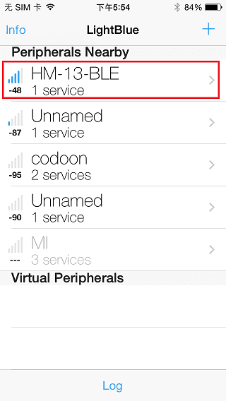
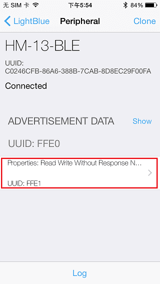
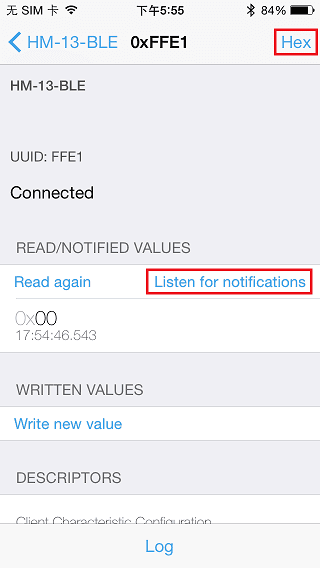
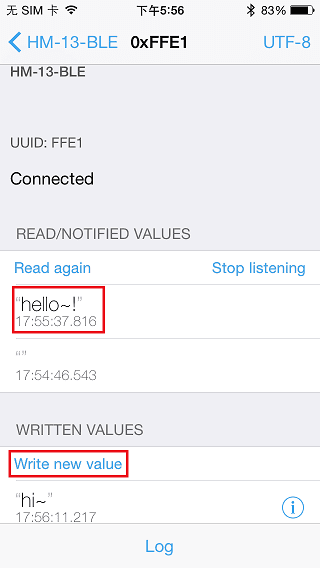
Power the Bluetooth and configure it as Peripheral role. Search LightBlue in Apple Store and install it. Launch the app, you may find “HM-13-BLE” which we just renamed. Touch it to connect, then touch “Properties” to control it. The key “Hex” on the top right is for change data format, maybe String is easy to see. Hit “Listen for notifications” to enable data receiving. Then we can send data to PC through BLE, hit “Write new value” and write some words. Also PC can transfer data to iPhone with serial terminal.
Data transmission between Two Arduinos
Are you ready to code? It’s time to do something after practice. Prepare a pair of Bluetooth, and Arduino or other platform to control them. Here we use two Arduino Uno. Set up the connection as mentioned in section “Hardware Installation”.
The program of Central and Peripheral use the same code, the only difference is the micro define at the beginning of the program. To assign the Bluetooth to Central role, Just need to modify the text to “#define MASTER 1”, or “#define MASTER 1” if Peripheral role was assigned.
The initialization program flow please refer to the following flow chart. First of all we need to distinguish the presetting baud rate of the Bluetooth. After this, send commands to restore factory settings, and change baud rate from 115200 to 9600 since software serial will not working well at high baud rate. Then other parameters were configured to the Bluetooth with Reset command in the final.
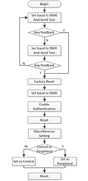
After the initialization, the Central and Peripheral will do different things, the Central will send message to Peripheral interval and print what received from Peripheral while the Peripheral only responds the Central.
Click here to download the test code and open HM-13_SW.ino with Arduino IDE, compile and download to Arduino Uno. Remember to configure the Bluetooth to different role by modify the macro at the beginning. If you have any problem about how to start Arduino, please click here for some help.
After downloading program, open two serial terminal windows, the LEDs on Bluetooth will flash, several seconds later, they stop to flash and keep on, this indicates that they connected to each other. According to the program is written, the Central sends message to the Peripheral continually and get feedback every time.
Resources
Support
If you have questions or other better design ideas, you can go to our forum or wish to discuss.