AVR Programming
ATMEL’s AVR Series of Microcontrollers is a very good option for those who wish to use the microcontrollers to their true potential, exploiting every bit of functionality they can offer. Learning them requires you to sometimes indulge into the internal aspects of microcontrollers. Registers, Binary Numbers all play a major role in operating these microcontrollers in their hardcore form. They form the heart of the Arduino Microcontrollers you might have learned earlier.
The AVR Series has many microcontrollers which vary in their processing capacity(Speed) and Memory. Throughout this tutorial we shall consider ATMega16 as our sample.
(ATMega32: 8-bit AVR Processor, 16 kbytes flash memory)
Contents:
- 1: Installation
- 1.1: Download Atmel Studio
- 1.2: Install Drivers
- 1.3: Install on Linux
- 2.1: Pins
- 2.2: Registers
- 2.3: Using the Datasheet
- 3.1: Controlling Output
- 3.2: Reading Input
- 4.1: Boolean Algebra
- 4.2: Bit Shifting
- 4.3: Bit Masking
- 5.1: Pre-scaling
- 5.2: Registers for controlling timers/counters
- 5.3: LED Blink Code
- 6.1: Timer triggered interrupt
- 9.1: Anatomy
- 9.2: Controlling the LCD
Installation
In order to write the code for AVR, and to burn it to the microcontroller, we use the software provided by ATMEL: ATMEL Studio.
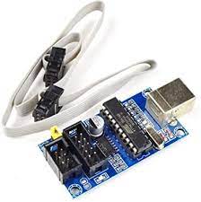
We also need something that connects the microcontroller and the computer (by USB). This was very simple in case of Arduino because among its peripherals, there was an in-built USB slot. Here we will use a “Development Board”.
In the picture above, observe 2 main things:
- The Programmer, which is plugged in the computer USB slot: It is used for the development board-to-USB Slot interface.
- The Development Board: Provides an interface to connect pins with Jumpers to further circuitry and with the input of the programmer.
After this let us move on to installation of ATMEL Studio.
Download Atmel Studio
Install Drivers
After installing Atmel Studio 7, we need to install Drivers for the programmer. Refer to the following videos for the procedure.
And for configuring the USBasp tool: Microcontroller Installing Atmel Studio
Atmel Studio has the environment for writing and compiling the code for AVR Microcontrollers, but in order to program the microcontroller with a programmer (the chip with an LED at the USB slot in the above picture), we need to configure the software with a new tool. For this configuration, we must set up avrdude (Video 1).
Now, for configuring the USBasp tool we need to set certain things since it is different than the normal USBs which we use at the ports. For this we need to configure the new external programming tool as specified in Video 2.
These two steps are very important and it will not be possible to write the code to the AVR Microcontroller properly without getting these configurations right. Refer the given links properly and if you have any doubts you can ask on the Electronics Club Gitter Rooms.
Installation for Linux
You need to install three packages, gcc-avr , avr-libc and avrdude for compiling and burning to AVR microcontrollers
On ubuntu you can run the command
After that we have prepared a Makefile to compile and burn AVR code on linux. You can download the Makefile here.
Copy this Makefile into your project folder and open it in a text editor. You need to edit the first line of the file to be PROJECT = <filename> . For eg. if the name of your main C file is test.c , your first line should be
to compile the code and generate HEX file. Then run
to burn HEX file to AVR after connecting USBasp.
Basics of AVR
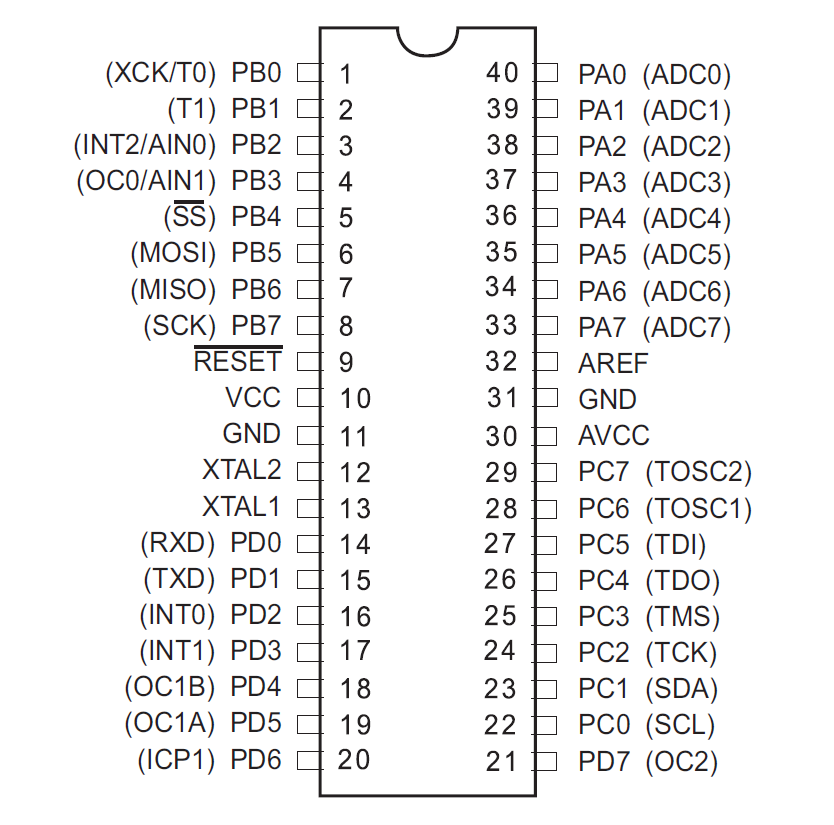
Confronting the Pin Diagram of ATMega16 at this stage can be a little dangerous for your enthusiasm, so please proceed slowly.
Apart from the Power pins, all the pins on AVR can be configured as Input or Output. These pins are present in four groups, or “Ports”, namely PortA, PortB, PortC, PortD. Every pin is given a name, like PA0,PB5 etc associated with its port. Besides every pin, its special function is mentioned in brackets. For example, all pins of PORTA can be used for ADC purpose apart from regular digital input/output. In this way each pin has a special function. So, we have 8×4=32 normal I/O pins, and 8 different pins meant for power supply, ADC voltage reference, reset etc.
Pinout for ATmega16
Registers
The microcontrollers(uC) use Registers to store the data describing the state(or mode) of certain operations(in most of our cases). For example, there is a register to store the “state/mode” of pins in every port, whether they are input or output pins. The Timer/Counter Control Registers(TCCR1A/B) store information regarding timers and counters(certain parameters etc). Similarly, there are many registers and they store bytes that control most of the functions of the microcontroller, so, the High/Low states of bits of those registers enable/disable interrupts, ADC etc.
The first register we will see is the one I just described. It is called the Data Direction Register(DDR). Hence DDRA is the register(8-bits of data) showing Input/output states of the 8 pins in port A.
Using the Datasheet
Though very intimidating to look at, the datasheet can provide you with just the right information if you know how to use it, and if you know that you have to use ‘IT’.
It is not at all necessary to read the complete datasheet, but there are portions in it which are at our level of understanding and there is also useful information which we will certainly need on our way.
It contains the code for every register, i.e. which bit of the register stores data for what function and lot of other information which we will use.
So keep the datasheet handy!
Controlling Input and Output
As stated earlier, one of the registers called Data Direction Register is used to control whether the pin acts as an Input pin or an Output pin.
Thus we have four 8-bit registers:
DDRA/B/C/D for controlling 8 pins each, of Ports A/B/C/D.
The convention for setting the input/output bit is:
1 — Output pin i.e. Controlled by Microcontroller
0 — Input pin i.e. Controlled by external circuit
Controlling the Output
Now, for the Output Pins, in order to set them to the value we wish, we use another register PORTA/B/C/D. Thus PORTA is a 8-bit register, which stores the 8 bits corresponding to each pin of Port A(effectively only the Output pins) for whether to give it a HIGH or LOW state.
Let us convey all this through a code snippet.
Note: The order of pins is 76543210, i.e. Most Significant Bit corresponds to pin 7
This tells the microcontroller that:
- Line 1: Pins 0,2,3 of Port A should be declared as output pins and rest as input.
- Line 2: Pins 0,2 should should give HIGH(Vin) and 3 should give LOW(0) output.
The bits corresponding to input pins of present in PORTA don’t matter, that is PORTA is an Output only Register
Reading the input
For the input values, there is a similar Input only Register, PINA/B/C/D.
The values of inputs are stored onto this 8-bit register, and in the code, we use this register with the comparison operator.
Checks if the inputs on pins 7,6,5,4 and 1 are High,High,Low,Low and High respectively.
Bitwise Operations
Bit masking refers to accessing specific bits in a data and modifying them according to our needs. Bit operations are a way to implement masking.
Bitwise Operators available in C are: AND ( & ), OR ( | ), XOR ( ^ ) and NOT (
). There are also bit shift operators viz. Bit left shift ( << ) and Bit right shift ( >> ) operators.
Bitwise operators are the ones that are defined on 2 bits and hold for large binary number through bit-by-bit binary operations and defined on 2 bits.
Boolean Algebra
Works like regular logical AND(A.B). So, for PORTA = 0b01101111 = 0x6f and PORTB = 0b10011001 = 0x99 ,
) work in the same way. They are same as their logical functions for 2 bit operations, and for larger numbers(many bits) they are executed bit by bit using binary model for each bit pair(as shown in bitwise AND example).
Bit Shifting
As the name suggests these operation are used to shift the position of a bit by some particular places. If you use << then the bits are shifted to the left, and if you use >> then the bits are shifted to the right and the bits are shifted by the number of places return besides these symbols.
Binary Left Shift Operator
This shifts left operand value to left by number of bits specified in the right operand. In other words, Binary left shift moves bits to a specified number of places to the left. The least significant bit is appended with 0 and most significant bit is dropped. The value of the variable gets multiplied by 2 for every left shift that occurs.
Then PORTA << 3 = 01111000;
Binary Right Shift Operator
This shifts left operand value to right by number of bits specified by the right operand. The most significant bit is appended with 0 and least significant bit is dropped.The value of the variable gets divided by 2 for every right shift that occurs.
Usage in AVR
Bit Operations are used very often, wherever the logical operations are required.
Bit Shifting is very useful in setting only specific bits of registers without worrying about everything else on the register.
If you wanted to turn on the lowest bit on PORTA, then you can simply write a 1 to PORTA because a 1, in 8 bit binary, is really 00000001.
However, if you wanted to turn on the second lowest bit on PORTA, then an easy way to do it is with a bit shift:
Means the same as
Bit Masking
Bits in registers are given names. We will discuss TCCR1B later here, but for the time being assume that a register has a bit named CS10. The usefulness comes out of the fact that you can set the CS10 bit High just by executing:
That is, “CS10” acts as its numeric location on the register! Bit Masking is used to carry out operations on only specific bits from a number of many bits.
Instead of TCCR1B = 1<<CS10 | 1<<CS11 , It is better to write: TCCR1B |= 1<<CS10 | 1<<CS11 . It lets the other bits stay as they are(OR with 0) and only sets the selected bits high(from low).
Timers and Counters
The operations in any microcontroller are “sequential” at heart, and so they all rely on clock-pulses. Hence the microcontrollers have internal clocks that keep ticking at the given rate, irrespective of anything else happening around them. They can also use external clocks for this same purpose.
The timer and counter functions in the microcontroller simply count in sync with the microcontroller clock. But the counter has limitations due to its bit-capacity, i.e. a 8-bit counter can count only up to 256(or 0 to 255). So generally there is a 16-bit counter(65536 counts). The counts are stored in the most important Timer/Counter Register, TCNT1 (16-bit, by default).
Pre-scaling
Now compare the maximum count of a counter and the clock-ticks of a microcontroller. Standard AVR Microcontrollers generally operate at 1 Mhz, that is 1,000,000 ticks per second, which is much more than 65536!
Hence, we need “prescaling” to increase the time-range of one cycle of the counter(they start all over again after attaining the max value) to a time comparable to our physical time domain(seconds). Prescaling is a way for the counter to skip some clock ticks.
AVR Microcontrollers allow prescaling of: 8, 64, 256 and 1024.
So, by setting a “Prescaler” of 8, the counter counts only once for every 8 ticks of the microcontroller clock, i.e. it runs at F_CPU/8 ( F_CPU = Frequency of uC).
Registers for controlling timers/counters
The register TCCR1A and TCCR1B (Timer/Counter Control Registers) are used for this. Please refer the datasheet for the description of the registers.
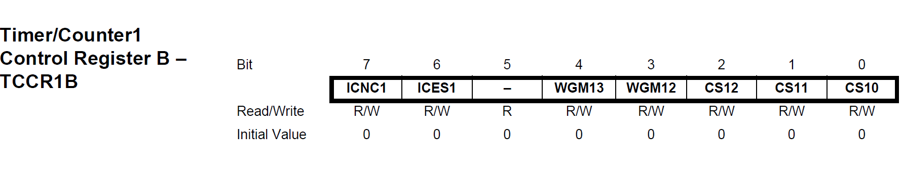
As you can see, all the 8-bits in the register are named.
(No need of knowing the function of all the 8 bits at this stage, the relevant ones will be discussed next)
Let us understand this through our first code on ATMEL Studio.
First code: LED Blink
Using the concepts learnt till now, we will write a program to toggle an LED 7 times a second.
We will proceed in a way in which you will have to, when you are doing it yourself. That is, we will use the Datasheet for reference instead of direct steps given to you.
How to choose the correct prescaler?
The uC ticks 1,000,000 times a second. We want to toggle the LED 7 times a second. So, we want the LED to toggle on every 142857th clock pulse. Now, since 65536 (highest value of count) is smaller than 142857, we want to set a prescaler such that “the highest count comes well after the time when the original uC clock reaches 142857” (Read this line twice :p). 8, 64 are suitable prescalers. Let us take 64.
Okay. I got the prescaler. Now how do I set that?
Search “prescaler” and after some experience you will know where to look, among the numerous results you get for “prescaler” :p.
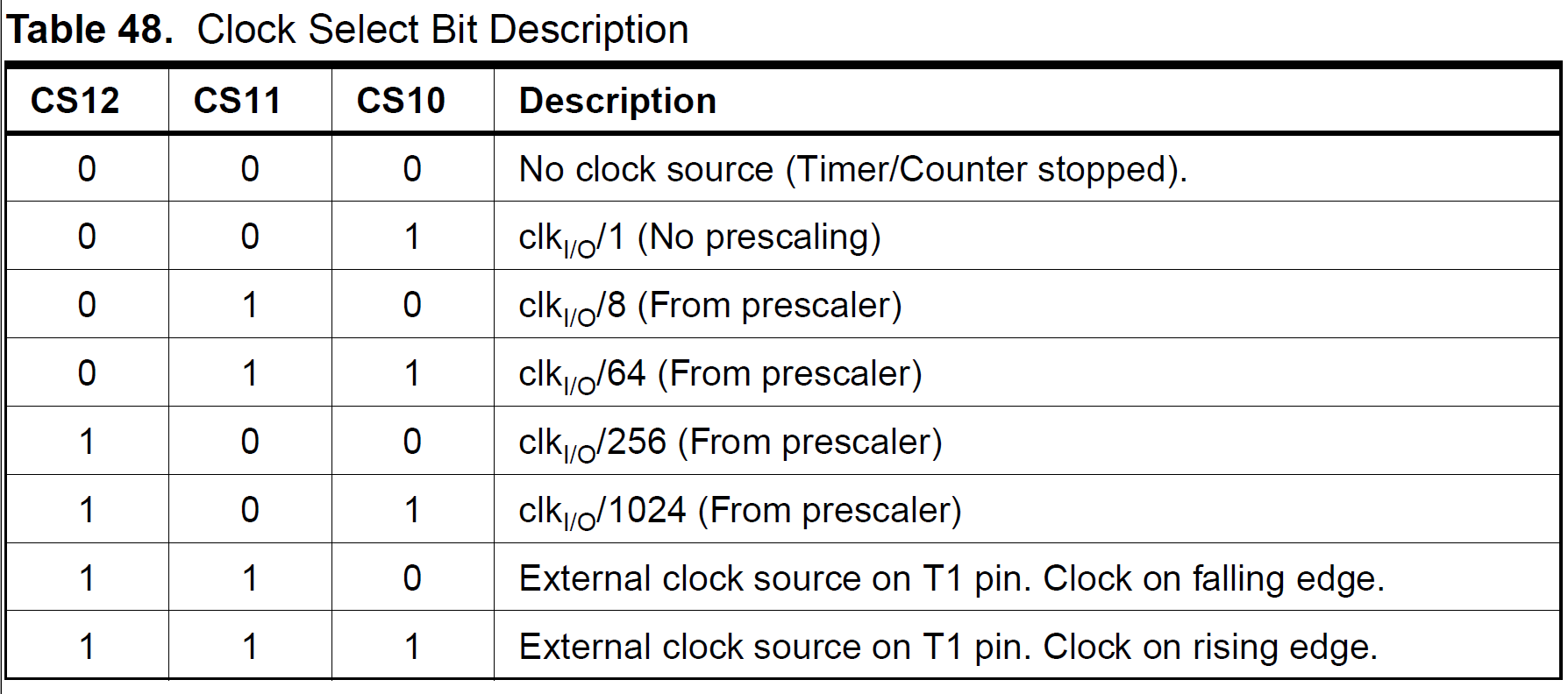
In the relevant table you will find the bit combination of CS12 / 11 / 10 required to set the prescaler we want. In our case: CS12 / 11 / 10 = 0 / 1 / 1 respectively. So we set the bits accordingly, using concepts of bit shifting and bit masking as discussed earlier.
(I told you about TCCR1A / B earlier, but ideally you first discover CS12 / 11 / 10 and then find out that these bits are present on TCCR1B , going by the datasheet approach :p)
When to toggle the LED?
On every 142857th pulse of the uC clock. That is, when TCNT1 is at the 142857/64 = 2232 th count (for prescaler=64).
After this background have a look at the actual code required for this.
Theory of Interrupts
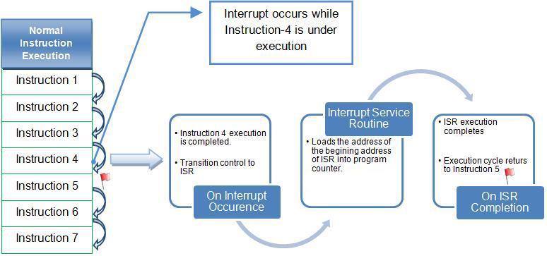
Interrupts are events that have the highest priority for the microcontroller(it pays immediate attention to them). That is, when an interrupt event occurs, the microcontroller Pauses its current task and attends to the interrupt. This is done by executing a routine called Interrupt Service Routine(ISR). At the end of the ISR, the microcontroller returns to the task it had paused and continues normally. So ISR or Interrupt Handler is the piece of code that must be executed when an interrupt is triggered.
Now, for enabling the execution of interrupts, we need to give appropriate values to certain bits, in certain specific registers. One compulsory bit is the Global Interrupt Enable bit. That is, when an interrupt flag is raised, the global interrupt bit must be High, in order to forward that interrupt request. So it is like an And-filter: “Request an interrupt if that specific interrupt flag is raised AND the global interrupt is enabled.”
A “flag” is like the abstract-physical representation of a bit for an event :p
Apart from the global interrupt enable bit, we have interrupt enabling bits for all the ways in which interrupts can be triggered. They can be triggered through the following ways:
- ADC
- Timer matching a given count
- Pin being High/Low
- Serial Communication
Timer triggered interrupt
Now let us apply our theory in writing a code for triggering an interrupt when the timer reaches a certain count.
We still need to know about the specific bits to be set for triggering an interrupt by comparison with timer. This is done by Clear Timer on Compare Mode.
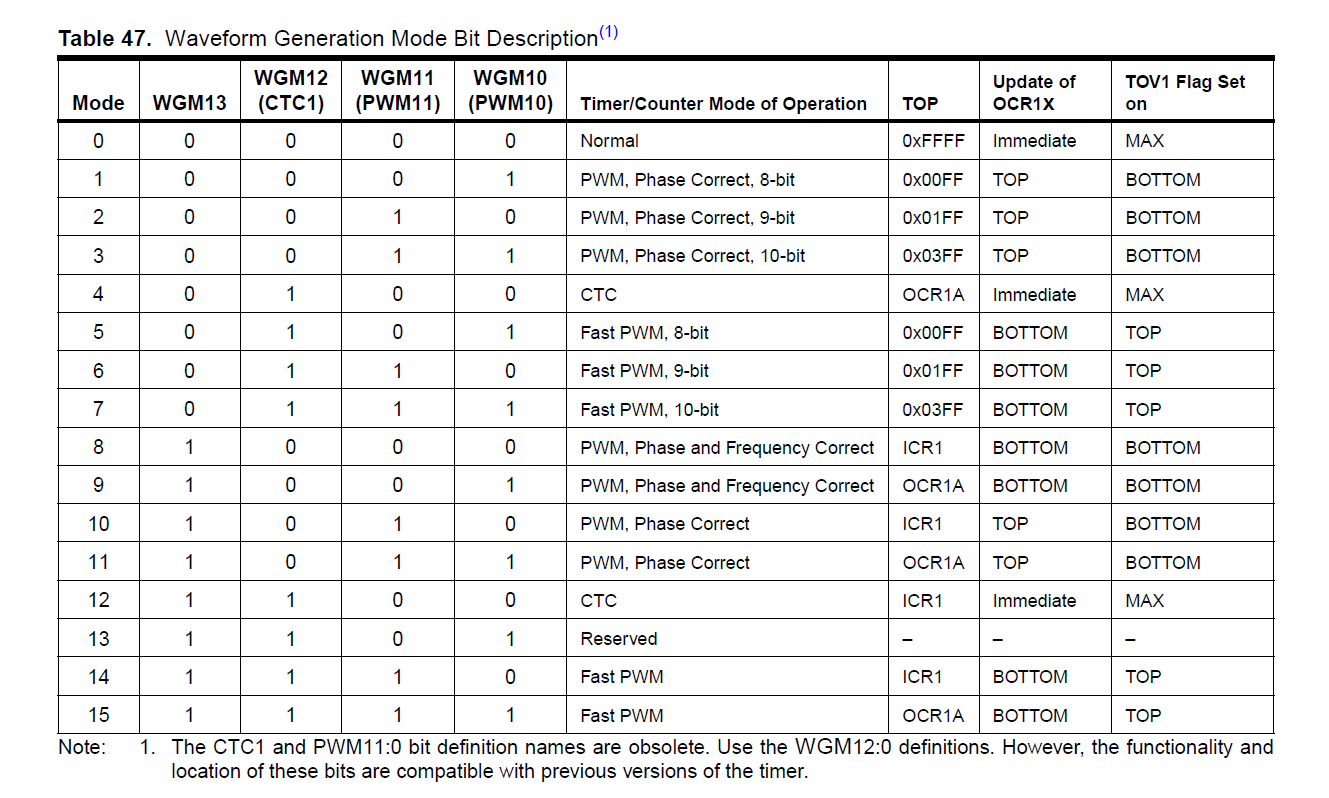
See option 4. This mode clears(resets) the timer on matching with a given value.
We also need to enable the time-match-triggered interrupt.
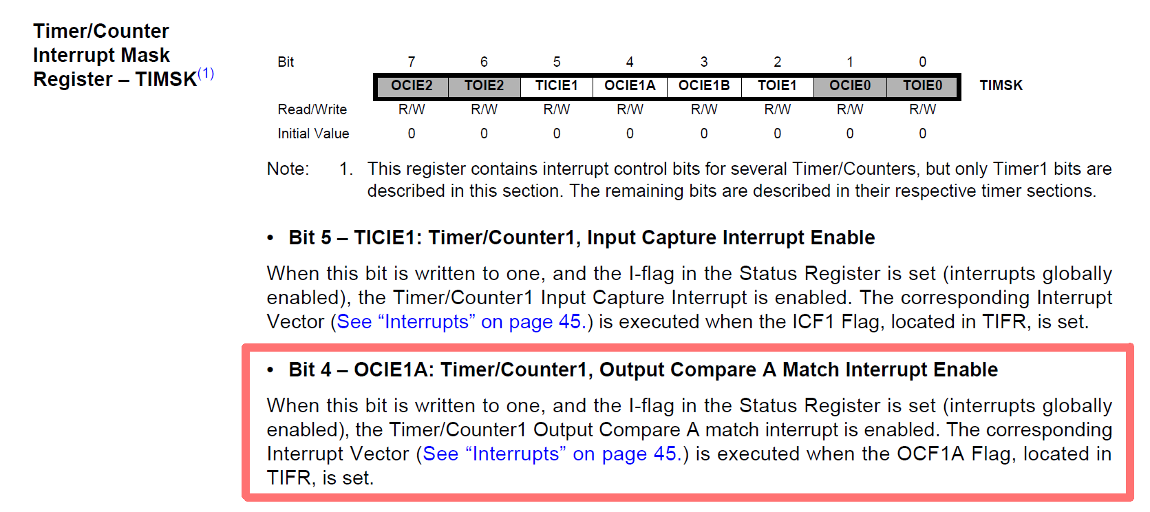
We will set OCIE1A bit High, thus enabling it. So, when the timer reaches the value specified(stored) in OCR1A , timer will be cleared (“Clear on Compare”) and the Output Compare Match Interrupt Enable becomes high (Interrupt flag raised).
Once the and interrupt is requested(global interrupt must be enabled), uC will go into the ISR, so we will specify the code for the ISR also.
Analogue-Digital Conversion
Microcontrollers are capable of detecting binary signals i.e is the button pressed or not?.
It interprets five volts as 1 and zero volts as 0. The world however is not so simple and likes to use shades of gray. What if the signal is 2.72V? A 5V analog sensor may output 0.01V or 4.99V or anything inbetween. Microcontrollers have a device built into them that allows us to convert these voltages into values that we can use in a program to make a decision.
The ADC reports a ratiometric value. This means that if the ADC is a 10 bit ADC then it assumes 5V is 1023 and anything less than 5V will be a ratio between 5V and 1023. Hence we can see analog to digital conversions are dependant on the the reference voltage(which is by default the system voltage).
In microcontrollers we have the flexibility of setting the reference analog voltage for the ADC.There’s a pin available on the microcontroller called as AREF which can be set to desired values and you can have your customized ADC. For example in a 10 bit ADC if the input voltage is equal to AREF then the ADC output is 1023. If the input voltage is less than AREF voltage then the ADC output is somewhere between 0 — 1023.
As you know, we need to set certain bits in some registers in order to use ADC.
- ADC Multiplexer Selection Register ( ADMUX ): For selecting the reference voltage and the input channel.
- ADC Control and Status Register A ( ADCSRA ): As the name says it has the status of ADC and is also used for controlling it.
- ADC Data Register ( ADCL and ADCH ): The final result of conversion is here.
Here’s the logic flow for algorithm for using ADC:
- Enable global interrupts
- Selecting the correct clock frequency for maximum resolution ( 50 – 200 KHz)
- Selecting the input pin
- Set the ADC Interrupt Enable
- Enabling the ADC
- Start the ADC conversion
The descriptions of these registers, and the relevant tables for deciding the bit combinations as given in the datasheet are shown below.
Based on the tables that follow, which bits are set to what value for achieving what setting is mentioned in the code comments.
Atmel studio как прошить микроконтроллер
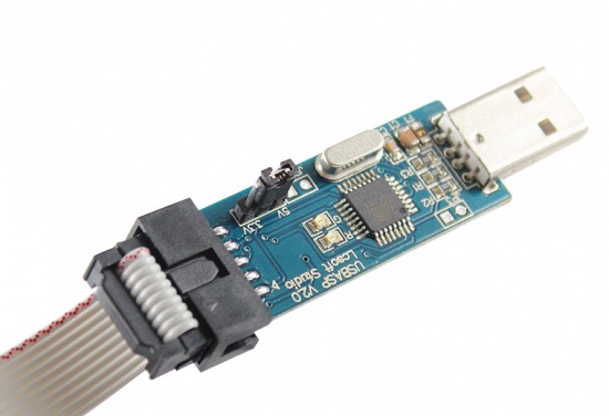
In this tutorial you will be learning how to use Microchip Studio (previously known as Atmel Studio) to program an AVR microcontroller over UART using the Optiboot bootloader. The hardware necessary is very inexpensive. All you need is an ISP (In System Programming) module such as USBTinyISP (around 3$) and an USB to Serial adapter that is around the same price and you can even build it yourself if you wish.
Contents
Hardware requirements
ISP module such as USBTinyISP, USBASP.
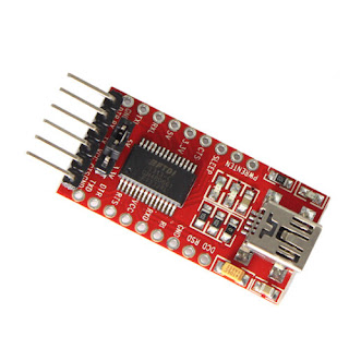
USB to Serial adapter also known as FT232 module, USB to TTL. If you wish to build one yourself you can find a tutorial here https://www.programming-electronics-diy.xyz/2018/02/how-to-build-your-own-usb-to-uart.html.
A microcontroller: in this tutorial I will be using ATmega328PB but the concepts apply to other microcontrollers as well.
Burning the Optiboot Bootloader
Initially an AVR microcontroller can be programmed over SPI using the pins called MOSI, MISO, SCK and RESET. But most often you will need to transfer data from PC to microcontroller and vice-versa, using UART, for debugging purposes or data logging. That will require two modules — one for ISP and one for Serial — and that is not optimal. By using a bootloader the UART can be used for both programming and PC interface.
A bootloader is just some code that resides in a special area of the flash memory that can accept the application code over UART and write it on the application flash section.
There are many bootloaders but in this tutorial I will be using this Optiboot version because it has auto baud rate detection so you can use any speed to upload the code and has compiled files for ATmega328P and ATmega328PB. The make file can be modified for other types of microcontrollers and CPU frequencies but that requires some knowledge on the topic.
To upload the bootloader we will be using the latest version of avrdude for Windows. Note that if you have WinAVR installed, the PATH must be modified so it can use this version instead the one that comes with WinAVR. This is because the WinAVR uses an older version. The second reason and most important is that this version is compiled using libftdi that adds support for FTDI devices.
After downloading avrdude, extract the files in a folder of your choice.
Adding avrdude to Windows System PATH
For easy access of avrdude when using command prompt and Microchip Studio, first we need to let Windows know where avrdude executable is located. To do this press the Windows key or Start button and type «path«. Now you should see «Edit the system environment variables«. Clicking on the result will open the System Properties window in the Advanced tab. Next click on Environment Variables.

In the second box select Path and click Edit then New and paste the path to the folder where avrdude is located. To obtain the folder path, navigate to the folder and right click on the folder name in the top navigation bar and select Copy address as text.
To check if Windows can find avrdude, press Windows key then type «cmd» and click on Command Prompt. Finally, type avrdude and press enter. Now you should see a list of available avrdude options.
Uploading the bootloader using SPI
The next step is to upload the Optiboot bootloader using an ISP module connected to SPI and the good old avrdude that can be accessed using the executable name and some arguments in a Command Prompt window. The cmd window must be opened from where the Optiboot hex files are so the avrdude can find them. To do this navigate to the Optiboot folder, pres CTRL+L then type cmd and press enter.
The avrdude parameters for ATmega328PB are:
avrdude -c usbtiny -B 10 -p atmega328pb -e -U flash:w:optiboot_m328pb.hex:i -U lfuse:w:0xFF:m -U hfuse:w:0xD2:m -U efuse:w:0xFF:m -U lock:w:0xCF:m
avrdude — the executable name
-c — programmer type. Here I use usbtiny. Type avrdude -c ? for a list of available programmers.
-B — bit clock period in us. Programming speed. A value of 10 works fine for a 16MHz crystal.
-p — AVR device.
-e — perform a chip erase.
-U — used to read/write the chip.
- flash indicates the memory type.
- w means we want to write that location instead of reading (r).
- After w: is the name of the hex file that you want to write to the microcontroller and in this case is the bootloader. Make sure you select one for your particular microcontroller. The versions that have _blink in the filename will blink a led to indicate that the bootloader works. If this is not an Arduino board, you need to connect the led through a resistor to the pin that will be toggling. The pin depends on the microcontroller and for ATmega328PB the pin was PB5.
The fuses
It is very important that you select the right fuse settings as wrong settings can make the microcontroller unusable unless you have a high voltage programmer. There are 4 fuse types: low fuse, high fuse, extended fuse and lock fuse denoted as: lfuse, hfuse, efuse and lock. I have used this site to calculate the fuse bits for the ATmega328PB that are used in the above command. On the website there is no ATmega328PB but ATmega328P works too.
The description of the fuse bits are as follows:
- divide clock by 8 is disabled
- the CPU clock is sourced from external crystal greater than 8MHz (16MHz in this case)
512 words are allocated for the bootloader and the boot start address is $3E00- 1024 words are allocated for the bootloader and the boot start address is $3C00. After some time the bootloader was getting corrupted and I believe that 512 words wasn’t enough
- Boot Reset Vector enabled
- Preserve EEPROM memory through the chip erase (optional)
- Serial program downloading (SPI) enabled
- Watch-dog Timer disabled (optional)
- Brown-out detection disabled (optional)
- Boot loader protection mode 3: LPM and SPM prohibited in Boot Loader section. This is to prevent the application code modifying the boot loader from what I understand.
If you are using a different microcontroller or other fuse bits settings you need to update the fuse hex values with the ones obtained from the online calculator. Now all you have to do is to paste the command in the cmd window and press enter to burn the boot loader. If everything was successful, now you can program the microcontroller using the UART instead of SPI.
Programming the ATmega328PB using the Boot Loader, FTDI adapter and Microchip Studio
Microchip Studio (previously known as Atmel Studio) is a very good platform for programming AVR devices and not only. Since it’s a very feature-rich application, it can be overwhelming for a beginner but if you focus only on what you need it’s very easy to use.
Wiring the USB to Serial
The pin port and numbers where the UART is located can be found in the datasheet in the «Pin Configurations» chapter.

On ATmega328PB the transmit pin (TXD0) is on PD1 and receive pin (RXD0) is on PD0. Connect TXD0 to RX on the serial module and RXD0 to TX of the module. The DTR pin of the serial adapter must be connected to the Reset pin of the microcontroller through a 100n capacitor. When the DTR is pulled low it will reset the microcontroller, then the bootloader will be ready to accept the application code.
Creating a new project inside the Microchip Studio
A new project can be created using the File -> New -> Project.

Here, select GCC C Executable Project, select the desired folder location and give it a name.
In the next step search for atmega328pb and select it from the list.
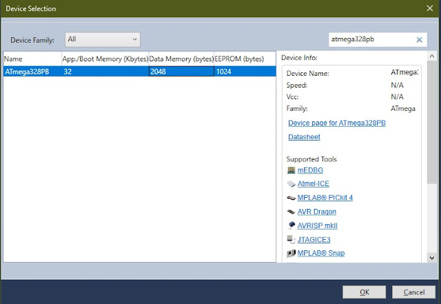
That’s it! After pressing OK the project will be created. In the Solution Explorer window you can open the project files or create new ones. For now we only have the main.c and as the name suggests is the main file that will include other files. The main.c has a function called main and inside is a while loop.
When the microcontroller starts, the code will be executed from top to bottom. The while loop will run as long 1 is 1 which means forever. Before the loop you usually put initialization functions or code that must run only once after the microcontroller starts.
Blinking a led code
First choose a port and pin where to connect the led. Then that pin must be set as output high or low. More on configuring the microcontroller pins can be found here.
Assuming the led in on port B pin 4 the code looks like this:
Pin 4 of port B is set to 1 (high) and data direction register is also set to 1 (meaning output) for pin 4 keeping the rest of the pins as they were. Then in the while loop the pin is toggled — if it is low it will be high and if it’s high it will be low. Between each toggle there is a delay of 1000 milliseconds.
Compiling the code
To generate the hex file use the Build -> Build Solution or just press F7. The Output window should open with the warning message that the F_CPU is not defined and that is because the delay.h needs to know our CPU frequency in order to calculate how many CPU cycles of do-nothing to count. You will find out that this define will be needed by many other libraries so let’s define it like so:
This must be placed before the includes. Now the output window should look like this:

Notice that we have used 248 bytes of flash memory and 0 bytes of SRAM.
Uploading code to microcontroller over UART
The standard way is to use a programmer from Atmel and that way you can benefit from many features such as debugging, burning fuses, seeing the code execution in real time, adding code break points, etc. But if you only have a cheap USB to Serial and want to experiment with it, you can still use it with Microchip Studio by using the External Tools.
To add an external tool use Tool — > External Tools:

If you have added tools previously, they will appear above External Tools. This list is available for all projects so make sure you add a suggestive name that indicates the programmer type, microcontroller and whether is for the Debug or Release folder.

- Title is the desired name of the custom programming tool.
- Command: application used for programming — avrdude.exe.
- Arguments: arguments for avrdude.
-c arduino -p atmega328pb -P COM3 -b 115200 -U flash:w:$(ProjectDir)Debug\$(TargetName).hex:i
c: programmer type. I use a custom module made using the FT232 ic but none of the programmers that had FTDI in the name worked for me except for arduino. Don’t know why it works but it does.
P : the USB port where the programmer is. Use Device Manager in Windows and check the Ports with the programmer plugged in to see the port number. Mine was on COM3.
b: UART baud rate
For the Release folder, replace Debug with Release. Also be sure to check the «Use Output Window» to be able to see the output from avrdude in the Microchip Studio output window.
That’s it. Now you can upload the code over UART just by pressing on the external tool that you have created.
Использование программатора USBASP в Atmel Studio
Программатор USBASP является на сегодняшний день самым дешевым программатором микроконтроллеров AVR компании ATMEL и позволяет программировать большое множество микроконтроллеров серий AVR ATTiny, AVR ATMega и других. В данной статье я расскажу вам об основных особенностях использования этого программатора из под ОС Windows 7 и как настроить его работу совместно со средой разработки программ Atmel Studio на примере версии 6.1. К сожалению, по умолчанию, Atmel Studio не поддерживает этот программатор.
Установка драйвера программатора
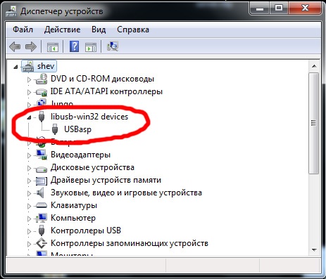
В первую очередь необходимо установить драйвер для программатора. Мы не будем подробно описывать процедуру установки драйвера, так как тут не должно возникнуть каких либо трудностей. После установки драйвера подключенный программатор отображается в диспетчере устройств Windows как устройство USBasp.
Установка Avrdude
Для программирования микроконтроллеров AVR будем использовать программу Avrdude. Эта программа поддерживает большое количество программаторов, в том числе и USBASP. Этой программе посвящена отдельная страница в википедии.
Программа avrdude является консольной и запускается из командной строки. Для выполнения программирования ей передается набор параметров, определяющий настройки. Ниже приведен пример командной строки для программирования контроллера при помощи программатора USBASP:
Поясним основные параметры:
- -c usbasp параметр определяет тип программатора, в нашем случае это usbasp;
- -p atmega32 параметр определяет тип микроконтроллера, для примера использован ATmega32;
- -U flash:w:myhexfile.hex параметр определяет hex файл для записи в контроллер. Файл должен располагаться либо в каталоге программы, либо необходимо указать полный путь к файлу;
- -U lfuse:w:0x6a:m параметр определяет младший байт регистра Fuse;
- -U hfuse:w:0xff:m параметр определяет старший байт регистра Fuse;
Регистры Fuse используются для настройки режима работы микроконтроллера и для их определения обратитесь к документации соответствующего контроллера. Хочу предупредить, что некорректная установка режима контроллера через регистры Fuse может привести к невозможности дальнейшего программирования контроллера, по этому, внимательно изучите документацию. Если вы не хотите изменять регистр Fuse, вы можете не передавать эти параметры при программировании, в этом случае регистр Fuse останется в том же состоянии, что и до программирования.
Avrdude имеет много разных функций, но в рамках данной статьи нам важен один режим ее работы, а именно заливка программы в микроконтроллер. Остальные функции вы сможете изучить в документации.
Настройка программирования из Atmel Studio
Как уже было упомянуто, Atmel Studio не поддерживает программатор USBASP. Однако в нее встроен механизм для запуска внешних программ для выполнения различных действий. Используя данный механизм внешних инструментов, программирование контроллера будет осуществляться одной кнопкой прямо из меню Atmel Studio.
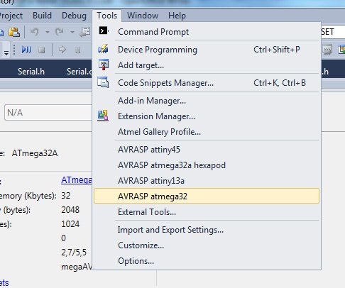
В Atmel Studio открываем пункт меню Tools и выбираем пункт External tools.
В открывшемся окне настройки инструментов нажимаем кнопку Add для добавления нового инструмента. Заполняем следующие поля:
- Title: произвольное имя инструмента, мы указали USBASP atmega32.
- Command: файл запуска программы avrdude. Мы указали C:AVRDUDEavrdude.exe, так как у нас она размещена в каталогеAVRDUDE на диске С.
- Arguments: параметры запуска для avrdude, которые мы рассмотрели выше. Мы задали строку -c usbasp -p atmega32 -U flash:w:$(TargetName).hex, в которой указали имя программатора, имя контроллера, и путь к файлу прошивки. Путь к файлу указан через специальные макросы и Atmel Studio подставит их сама. Мы не указали регистр Fuse в этом примере, но при необходимости вы можете добавить их самостоятельно.
- Initial directory: указан макрос для подстановки каталога, в котором находится файл прошивки.
- Use Output window: установите эту галочку для того, что бы результат работы программы показывался в окне Atmel Studio. Послу установки всех настроек нажмите кнопку OK для сохранения настроек и выхода.
Теперь, для программирования микроконтроллера достаточно зайти в меню Tools и нажать команду USBASP atmega32, которая там должна появиться после проделанных настроек. Программирование необходимо запускать после компиляции проекта, так как файл прошивки создается в процессе компиляции проекта.
Подключение программатора к микроконтроллеру
Программатор USBASP подключается к микроконтроллеру по стандартному интерфейсу ISP. Физически на программаторе интерфейс имеет 10 контактов. Большинство контактов объединены общим проводом. Назначение используемых контактов следующее:
- MISO, MOSI, SCK, RESET — подключается к соответствующему выводу микроконтроллера;
- GND – земля, подключается к мину или GND микроконтроллера;
- VCC – используется для подачи питания на микроконтроллер.
На печатных платах модулей, где используются контроллеры AVR, разработчики очень часто располагают интерфейс SPI 6 контактов, позволяющий произвести внутрисхемное программирование контроллера. Такой интерфейс можно видеть даже на платах Arduino. Для подключения программатора к такому 6-и контактному интерфейсу можно использовать соединительные провода мама-мама или специальный переходник ISP10 в ISP6 для программатора AVR USBASP.
Программирование микроконтроллеров в AtmelStudio 6. Часть 1. Первые шаги

Если вы читаете эту статью, вероятно у вас возникло желание понять, как работают микроконтроллеры, и скорее всего появились вопросы:
1. Какой микроконтроллер выбрать для работы?
2. Какую среду разработки использовать для программирования выбранного микроконтроллера?
3. Как прошивать контроллер, и какие дополнительные приборы и акссесуары нужны для удобной работы с ними?
4. Какую литературу изучать?
5. Где в интернете можно задавать вопросы и получать конкретные ответы?Попробуем ответить на эти вопросы.
↑ 1. Какой микроконтроллер выбрать для работы?
Большой популярностью у радиолюбителей пользуются 8-битные микроконтроллеры PIC фирмы Microchip Technology и AVR фирмы Atmel, 16-битные MSP430 фирмы TI, а также 32-битные микроконтроллеры, архитектуры ARM.
В промышленности, несколько иначе, первое место с большим отрывом занимает Renesas Electronics на втором Freescale, на третьем Samsung, затем идут Microchip и TI, далее все остальные.
Популярность определяется ценой и доступностью, немалую роль играют наличие технической информации и стоимость программного сопровождения.Мы будем изучать 8-битные микроконтроллеры AVR, семейства ATMEGA 8 и 16 серии. Выбор определился, опять же доступностью, наличием множества любительских разработок, огромным количеством учебного материала. Наличием разнообразных встроенных компонентов и функциональностью этого семейства.
↑ 2. Какую среду разработки использовать для программирования выбранного микроконтроллера?
Для AVR созданы разные интегрированные среды разработки (IDE, Integrated development environment).
IDE – это система программных средств, используемая программистами для разработки программного обеспечения (ПО), в состав которой входят:
• текстовый редактор,
• компилятор и/или интерпретатор,
• средства автоматизации сборки,
• отладчик.Наиболее распространенные из них AVRStudio, ATmelStudio, WINAVR, CodeVision, IAR Embedded Workbench.
Для того, чтобы писать программы, мы воспользуемся бесплатной IDE ATmelStudio версии 6 и выше.
Скачать Atmel Studio можно с официального сайта после регистрации (регистрация абсолютно бесплатная и ни к чему не обязывает!)ATmelStudio позволяет создавать проекты, и писать программы как в ассемблере, так и на СИ.
Изначально всегда стоит вопрос: какой язык программирования выбрать, чтобы писать эффективные программы?
Отвечу просто: нужно уметь писать как минимум на двух языках ассемблере и СИ. Ассемблер просто необходим, когда нужно написать быстрые и компактные подпрограммы и макросы, различные драйверы устройств. Но, когда требуется создать объемный проект, построенный на сложных алгоритмах, без знания СИ может быть потрачено очень много времени, особенно в процессе отладки, а если возникнет желание перенести на другую платформу, например PIC18, или STM, может стать неразрешимой проблемой.
Кроме этого, сейчас появились аппаратные вычислительные платформы Arduino, работа с которыми требует знаний языка СИ++.
Поэтому будем писать программы как в ассемблере, так и на СИ.Чтобы наглядно видеть результат своей работы, не используя паяльник или макетную плату достаточно установить программу Proteus.
↑ 3. Как прошивать контроллер, и какие дополнительные приборы и акссесуары нужны для удобной работы с ними?
Используем датагорский кит — программатор Project-005 «D-AVR910». Кроме этого, нужно будет приобрести макетные платы, блок питания с выходным напряжением 5 Вольт. Можно в качестве БП с малыми пульсациями использовать наш кит Project-006 «POWER FILTER», применив стабилитрон на 5 Вольт.
Возможно, со временем мы с Игорем предложим проект для сборки отладочной платы.


↑ 4. Какую литературу изучать?
А вот, например:
• Практическое программирование AVR на ассемблере. Ревич, 2011
• 1000 и одна микроконтроллерная схема Вып. 1-2. Рюмик, 2010-2011
• 10 практических устройств на МК AVR Книга 1-2. Кравченко, 2008-2009
• Самоучитель разработчика устройств на МК AVR. Белов, 2008
• МК AVR семейств Tiny и Atmega. Ефстифеев, 2008
• CodeVisionAVR. Пособие для начинающих. Лебедев, 2008
• Микропроцессорное управление устройствами, тиристоры, реле. Белов, 2008
• Аналоговые интерфейсы МК. Стюард, Болл, 2007
• Создаем устройства на МК AVR. Белов, 2007
• МК AVR в радиолюбительской практике. Полный разбор ATTINY2313. Белов, 2007
• Сетевой и межсетевой обмен данными с МК. Иди, 2007
• МК AVR. практикум для начинающих. Хартов, 2007
• Применение AVR Схемы, алгоритмы, программы. Баранов, 2006
• Микроконтроллеры AVR. Вводный курс. Мортон, 2006
• Измерение, управление и регулирование с помощью AVR. Трамперт, 2006
• Программирование на языке С для AVR и PIC МК. Шпак, 2006
• Конструирование устройств на МК. Белов, 2005
• МK — это же просто, тома 1-3. Фрунзе, 2002-2003
• Язык программирования Си, 2-е издание. Керниган, Ритчи, 2009
• Программирование микроконтроллеров ATMEL на языке С. Прокопенко, 2012↑ 5. Где в интернете можно задавать вопросы и получать конкретные ответы?
Задавать вопросы вы можете на нашем или любом другом форуме, где так или иначе затронуты темы по микроконтроллерам. Главное на форумах правильно формулировать вопросы, чтобы четко получать ответы. Абстрактные вопросы не приветствуются, и скорее всего вместо ответа вы получите жесткую критику, или ваш вопрос останется без внимания!
↑ Теперь рассмотрим поближе нашего фаворита, микроконтроллер ATMEGA 8
• 8-разрядный высокопроизводительный AVR микроконтроллер с малым потреблением
• Прогрессивная RISC архитектура
130 высокопроизводительных команд, большинство команд выполняется за один тактовый цикл
32 8-разрядных рабочих регистра общего назначения
Полностью статическая работа
Приближающаяся к 16 MIPS (при тактовой частоте 16 МГц) производительность
Встроенный 2-цикловый перемножитель• Энергонезависимая память программ и данных
8 Кбайт внутрисистемно программируемой Flash памяти (In-System Self-Programmable Flash)
Обеспечивает 1000 циклов стирания/записи
Дополнительный сектор загрузочных кодов с независимыми битами блокировки
Обеспечен режим одновременного чтения/записи (Read-While-Write)
512 байт EEPROM
Обеспечивает 100000 циклов стирания/записи
1 Кбайт встроенной SRAM
Программируемая блокировка, обеспечивающая защиту программных средств пользователя• Встроенная периферия
Два 8-разрядных таймера/счетчика с отдельным предварительным делителем, один с режимом сравнения
Один 16-разрядный таймер/счетчик с отдельным предварительным делителем и режимами захвата и сравнения
Счетчик реального времени с отдельным генератором
Три канала PWM
8-канальный аналого-цифровой преобразователь (в корпусах TQFP и MLF)
6 каналов с 10-разрядной точностью
2 канала с 8-разрядной точностью
6-канальный аналого-цифровой преобразователь (в корпусе PDIP)
4 канала с 10-разрядной точностью
2 канала с 8-разрядной точностью
Байт-ориентированный 2-проводный последовательный интерфейс
Программируемый последовательный USART
Последовательный интерфейс SPI (ведущий/ведомый)
Программируемый сторожевой таймер с отдельным встроенным генератором
Встроенный аналоговый компаратор• Специальные микроконтроллерные функции
Сброс по подаче питания и программируемый детектор кратковременного снижения напряжения питания
Встроенный калиброванный RC-генератор
Внутренние и внешние источники прерываний
Пять режимов пониженного потребления: Idle, Power-save, Power-down, Standby и снижения шумов ADC• Выводы I/O и корпуса
23 программируемые линии ввода/вывода
28-выводной корпус PDIP, 32-выводной корпус TQFP и 32-выводной корпус MLF• Рабочие напряжения
2,7 — 5,5 В (ATmega8L)
4,5 — 5,5 В (ATmega8)• Рабочая частота
0 — 8 МГц (ATmega8L)
0 — 16 МГц (ATmega8)отличия ATMEGA16 от 8
• 16 Кбайт внутрисистемно программируемой Flash памяти (In-System Self-Programmable Flash)• Интерфейс JTAG (совместимый с IEEE 1149.1)
Возможность сканирования периферии, соответствующая стандарту JTAG
Расширенная поддержка встроенной отладки
Программирование через JTAG интерфейс: Flash, EEPROM памяти, перемычек и битов блокировки• Четыре канала PWM / ШИМ
• 8-канальный 10-разрядный аналого-цифровой преобразователь
8 несимметричных каналов
7 дифференциальных каналов (только в корпусе TQFP)
2 дифференциальных канала с программируемым усилением в 1, 10 или 200 крат (только в корпусе TQFP)• Шесть режимов пониженного потребления: Idle, Power-save, Power-down, Standby, Extended Standby и снижения шумов ADC
• 32 программируемые линии ввода/вывода
• 40-выводной корпус PDIP и 44-выводной корпус TQFP


↑ AtmelStudio
Если Вы только начинаете, то нужно скачать и установить программу AtmelStudio с официальной страницы atmel.com
После установки программы AtmelStudio можно приступить к созданию проекта.
Проект – это ваша программа, которую вы будете писать, отлаживать и прошивать, после компиляции, в память микроконтроллера.Чтобы создать проект, надо открыть программу, появиться такая заставка,

и откроется страница создания проекта

Чтобы создать новый проект, нужно кликнуть по «New Project…»
В этом случае откроется новое окно, где можно выбрать язык программирования, название проекта, его месторасположение, название пакета с файлами проекта и возможность создания каталога для дальнейшего использования в других перекрестных проектах. Чтобы создать проект, где мы будем программировать в ассемблере, нужно выбрать — Assembler, после этого поменяем название проекта, его расположение, и выбираем ОК.
Появится следующее окно

Выбираем “megaAVR, 8-bit” и находим нужный нам микроконтроллер, мы выбрали ATmega8. В правой части заставки появляется список устройств, работающих с этим микроконтроллером, один из которых мы можем подключить. Выбираем ОК.

Появляется страница редактора текста, которая позволяет редактировать и отлаживать программу. Пока страница чистая, указано время и дата создания и название файла проекта, имя пользователя. Есть дополнительные окно устройств ввода-вывода, окно отчетов компиляции программы. Теперь мы


Выбираем семейство микроконтроллеров “megaAVR, 8-bit”

Далее, наименование микроконтроллера и выбираем ОК.
Появляется страница редактора текста. Здесь мы можем программировать в СИ.

У нас есть возможность загрузить демонстрационные проекты для работы с платами разработки, выпускаемыми корпорацией ATMEL.
Для этого нужно при создании проекта выбрать пункт “New Examle Project from ASF…”
Откроется окно следующего вида:

Здесь вы можете выбрать нужный проект, и экспериментировать как вам хочется…
Третий пункт на страничке создания проектов позволяет быстро открывать последний загруженный проект.
Так же есть возможность управлять проектом, для этого нужно выбрать название проекта под пунктом “Recent Projects” и кликнуть по правой клавише мыши. Появится меню из 3-х пунктов:

Open Project – запускает проект.
Open Containing Folder – просмотор содержимого папки проекта
Remove From List – удаление из списка проектов. Сам проект не удаляется, и попытка создать новый проект с таким же именем выдаст ошибку. Полностью удалить проект можно в папке, где он был создан.Как создается новый проект и про перенос старых проектов, созданных в AVR Studio 4, можно посмотреть на видеоролике от Александра Писанца