Arduino.ru
Микроконтроллеры Atmega, используемые в Arduino, содержат шестиканальный аналого-цифровой преобразователь (АЦП). Разрешение преобразователя составляет 10 бит, что позволяет на выходе получать значения от 0 до 1023. Основным применением аналоговых входов большинства платформ Arduino является чтение аналоговых датчиком, но в тоже время они имеют функциональность вводов/выводов широкого применения (GPIO) (то же, что и цифровые порты ввода/вывода 0 — 13).
Таким образом, при необходимости применения дополнительных портов ввода/вывода имеется возможность сконфигурировать неиспользуемые аналоговые входы.
Цоколевка
Выводы Arduino, соответствующие аналоговым входам, имеют номера от 14 до 19. Это относится только к выводам Arduino, а не к физическим номерам выводов микроконтроллера Atmega. Аналоговые входы могут использоваться как цифровые выводы портов ввода/вывода. Например, код программы для установки вывода 0 аналогового входа на порт вывода со значением HIGH:
pinMode(14, OUTPUT);
digitalWrite(14, HIGH);
Подтягивающие резисторы
Выводы аналоговые входов имеют подтягивающие резисторы работающие как на цифровых выводах. Включение резисторов производится командой
digitalWrite(14, HIGH); // включить резистор на выводе аналогового входа 0
пока вывод работает как порт ввода.
Подключение резистора повлияет на величину сообщаемую функцией analogRead() при использовании некоторых датчиков. Большинство пользователей использует подтягивающий резистор при применении вывода аналогового входа в его цифровом режиме.
Подробности и предостережения
Для вывода, работавшего ранее как цифровой порт вывода, команда analogRead будет работать некорректно. В этом случае рекомендуется сконфигурировать его как аналоговый вход. Аналогично, если вывод работал как цифровой порт вывода со значением HIGH, то обратная установка на ввод подключит подтягивающий резистор.
Руководство на микроконтроллер Atmega не рекомендует производить быстрое переключение между аналоговыми входами для их чтения. Это может вызвать наложение сигналов и внести искажения в аналоговую систему. Однако после работы аналогового входа в цифровом режиме может потребоваться настроить паузу между чтением функцией analogRead() других входов.
Arduino Nano: распиновка, схема подключения и программирование
Плата Arduino Nano — аналог флагманской Uno в миниатюрном размере. На ней предусмотрено всё необходимое для удобной работы с микроконтроллером: 14 цифровых входов/выходов (6 из них могут использоваться в качестве ШИМ-выходов), 6 аналоговых входов, кварцевый резонатор на 16 МГц, разъём Mini-USB, разъём питания, разъём для внутрисхемного программирования (ICSP) и кнопка сброса.
Видеообзор
Подключение и настройка
Для запуска платформы скачайте и установите на компьютер интегрированную среду разработки Arduino IDE.
При выборе платформы выбирайте Arduino Nano.
Если всё получилось — можете смело переходить к экспериментам.
Элементы платы
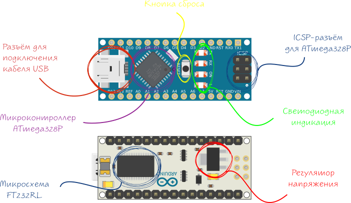
Микроконтроллер ATmega328P
Сердцем платформы Arduino Nano является 8-битный микроконтроллер семейства AVR — ATmega328P с тактовой частотой 16 МГц. Контроллер предоставляет 32 КБ Flash-памяти для хранения прошивки, 2 КБ оперативной памяти SRAM и 1 КБ энергонезависимой памяти EEPROM для хранения данных.
Микросхема FT232R
Микросхема FTDI FT232R обеспечивает связь микроконтроллера ATmega328P с USB-портом компьютера. При подключении к компьютеру Nano определяется как виртуальный COM-порт.
USB-UART преобразователь общается с микроконтроллером ATmega328P по интерфейсу UART через пины 0(RX) и 1(TX) . Рекомендуем не использовать эти контакты в своём проекте.
Светодиодная индикация
| Имя светодиода | Назначение |
|---|---|
| RX и TX | Мигают при обмене данными между Arduino Nano и ПК. |
| L | Пользовательский светодиод подключённый к 13 пину микроконтроллера. При высоком уровне светодиод включается, при низком – выключается. |
| ON | Наличие питания на Arduino Nano. |
Разъём Mini-USB
Разъём Mini-USB предназначен для прошивки платформы с помощью компьютера.
Регулятор напряжения 5 В
Линейный понижающий регулятор напряжения LM1117MPX-5.0 с выходом 5 вольт обеспечивает питание микроконтроллера ATmega328P и другой логики платформы. Максимальный выходной ток составляет 800 мА.
ICSP-разъём для ATmega328
ICSP-разъём предназначен для загрузки прошивки в микроконтроллер ATmega328 через программатор.
Также через контакты ICSP Nano общается с платами расширения по интерфейсу SPI.
Сколько аналоговых входов у ардуино atmega328
The Arduino Uno is a microcontroller board based on the ATmega328 (datasheet). It has 14 digital input/output pins (of which 6 can be used as PWM outputs), 6 analog inputs, a 16 MHz crystal oscillator, a USB connection, a power jack, an ICSP header, and a reset button. It contains everything needed to support the microcontroller; simply connect it to a computer with a USB cable or power it with a AC-to-DC adapter or battery to get started.
The Uno differs from all preceding boards in that it does not use the FTDI USB-to-serial driver chip. Instead, it features the Atmega16U2 ( Atmega8U2 up to version R2) programmed as a USB-to-serial converter.
of the Uno board has a resistor pulling the 8U2 HWB line to ground, making it easier to put into DFU mode.
of the board has the following new features:
- 1.0 pinout: added SDA and SCL pins that are near to the AREF pin and two other new pins placed near to the RESET pin, the IOREF that allow the shields to adapt to the voltage provided from the board. In future, shields will be compatible both with the board that use the AVR, which operate with 5V and with the Arduino Due that operate with 3.3V. The second one is a not connected pin, that is reserved for future purposes.
- Stronger RESET circuit.
- Atmega 16U2 replace the 8U2.
«Uno» means one in Italian and is named to mark the upcoming release of Arduino 1.0. The Uno and version 1.0 will be the reference versions of Arduino, moving forward. The Uno is the latest in a series of USB Arduino boards, and the reference model for the Arduino platform; for a comparison with previous versions, see the index of Arduino boards.
Summary
| Microcontroller | ATmega328 |
| Operating Voltage | 5V |
| Input Voltage (recommended) | 7-12V |
| Input Voltage (limits) | 6-20V |
| Digital I/O Pins | 14 (of which 6 provide PWM output) |
| Analog Input Pins | 6 |
| DC Current per I/O Pin | 40 mA |
| DC Current for 3.3V Pin | 50 mA |
| Flash Memory | 32 KB ( ATmega328 ) of which 0.5 KB used by bootloader |
| SRAM | 2 KB ( ATmega328 ) |
| EEPROM | 1 KB ( ATmega328 ) |
| Clock Speed | 16 MHz |
Schematic & Reference Design
Note: The Arduino reference design can use an Atmega8, 168, or 328, Current models use an ATmega328 , but an Atmega8 is shown in the schematic for reference. The pin configuration is identical on all three processors.
Power
The Arduino Uno can be powered via the USB connection or with an external power supply. The power source is selected automatically.
External (non-USB) power can come either from an AC-to-DC adapter (wall-wart) or battery. The adapter can be connected by plugging a 2.1mm center-positive plug into the board’s power jack. Leads from a battery can be inserted in the Gnd and Vin pin headers of the POWER connector.
The board can operate on an external supply of 6 to 20 volts. If supplied with less than 7V, however, the 5V pin may supply less than five volts and the board may be unstable. If using more than 12V, the voltage regulator may overheat and damage the board. The recommended range is 7 to 12 volts.
The power pins are as follows:
-
VIN. The input voltage to the Arduino board when it’s using an external power source (as opposed to 5 volts from the USB connection or other regulated power source). You can supply voltage through this pin, or, if supplying voltage via the power jack, access it through this pin.
Memory
The ATmega328 has 32 KB (with 0.5 KB used for the bootloader). It also has 2 KB of SRAM and 1 KB of EEPROM (which can be read and written with the EEPROM library).
Input and Output
Each of the 14 digital pins on the Uno can be used as an input or output, using pinMode(), digitalWrite(), and digitalRead() functions. They operate at 5 volts. Each pin can provide or receive a maximum of 40 mA and has an internal pull-up resistor (disconnected by default) of 20-50 kOhms. In addition, some pins have specialized functions:
-
Serial: 0 (RX) and 1 (TX). Used to receive (RX) and transmit (TX) TTL serial data. These pins are connected to the corresponding pins of the ATmega8U2 USB-to-TTL Serial chip.
The Uno has 6 analog inputs, labeled A0 through A5, each of which provide 10 bits of resolution (i.e. 1024 different values). By default they measure from ground to 5 volts, though is it possible to change the upper end of their range using the AREF pin and the analogReference() function. Additionally, some pins have specialized functionality:
- TWI: A4 or SDA pin and A5 or SCL pin. Support TWI communication using the Wire library.
There are a couple of other pins on the board:
-
AREF. Reference voltage for the analog inputs. Used with analogReference().
See also the mapping between Arduino pins and ATmega328 ports. The mapping for the Atmega8, 168, and 328 is identical.
Communication
The Arduino Uno has a number of facilities for communicating with a computer, another Arduino, or other microcontrollers. The ATmega328 provides UART TTL (5V) serial communication, which is available on digital pins 0 (RX) and 1 (TX). An ATmega16U2 on the board channels this serial communication over USB and appears as a virtual com port to software on the computer. The ’16U2 firmware uses the standard USB COM drivers, and no external driver is needed. However, on Windows, a .inf file is required. The Arduino software includes a serial monitor which allows simple textual data to be sent to and from the Arduino board. The RX and TX LEDs on the board will flash when data is being transmitted via the USB-to-serial chip and USB connection to the computer (but not for serial communication on pins 0 and 1).
A SoftwareSerial library allows for serial communication on any of the Uno’s digital pins.
The ATmega328 also supports I2C (TWI) and SPI communication. The Arduino software includes a Wire library to simplify use of the I2C bus; see the documentation for details. For SPI communication, use the SPI library.
Programming
The Arduino Uno can be programmed with the Arduino software (download). Select «Arduino Uno from the Tools > Board menu (according to the microcontroller on your board). For details, see the reference and tutorials.
The ATmega328 on the Arduino Uno comes preburned with a bootloader that allows you to upload new code to it without the use of an external hardware programmer. It communicates using the original STK500 protocol (reference, C header files).
You can also bypass the bootloader and program the microcontroller through the ICSP (In-Circuit Serial Programming) header; see these instructions for details.
The ATmega16U2 (or 8U2 in the rev1 and rev2 boards) firmware source code is available . The ATmega16U2 /8U2 is loaded with a DFU bootloader, which can be activated by:
- On Rev1 boards: connecting the solder jumper on the back of the board (near the map of Italy) and then resetting the 8U2.
- On Rev2 or later boards: there is a resistor that pulling the 8U2/16U2 HWB line to ground, making it easier to put into DFU mode.
You can then use Atmel’s FLIP software (Windows) or the DFU programmer (Mac OS X and Linux) to load a new firmware. Or you can use the ISP header with an external programmer (overwriting the DFU bootloader). See this user-contributed tutorial for more information.
Automatic (Software) Reset
Rather than requiring a physical press of the reset button before an upload, the Arduino Uno is designed in a way that allows it to be reset by software running on a connected computer. One of the hardware flow control lines (DTR) of the ATmega8U2 /16U2 is connected to the reset line of the ATmega328 via a 100 nanofarad capacitor. When this line is asserted (taken low), the reset line drops long enough to reset the chip. The Arduino software uses this capability to allow you to upload code by simply pressing the upload button in the Arduino environment. This means that the bootloader can have a shorter timeout, as the lowering of DTR can be well-coordinated with the start of the upload.
This setup has other implications. When the Uno is connected to either a computer running Mac OS X or Linux, it resets each time a connection is made to it from software (via USB). For the following half-second or so, the bootloader is running on the Uno. While it is programmed to ignore malformed data (i.e. anything besides an upload of new code), it will intercept the first few bytes of data sent to the board after a connection is opened. If a sketch running on the board receives one-time configuration or other data when it first starts, make sure that the software with which it communicates waits a second after opening the connection and before sending this data.
The Uno contains a trace that can be cut to disable the auto-reset. The pads on either side of the trace can be soldered together to re-enable it. It’s labeled «RESET-EN». You may also be able to disable the auto-reset by connecting a 110 ohm resistor from 5V to the reset line; see this forum thread for details.
USB Overcurrent Protection
The Arduino Uno has a resettable polyfuse that protects your computer’s USB ports from shorts and overcurrent. Although most computers provide their own internal protection, the fuse provides an extra layer of protection. If more than 500 mA is applied to the USB port, the fuse will automatically break the connection until the short or overload is removed.
Physical Characteristics
The maximum length and width of the Uno PCB are 2.7 and 2.1 inches respectively, with the USB connector and power jack extending beyond the former dimension. Four screw holes allow the board to be attached to a surface or case. Note that the distance between digital pins 7 and 8 is 160 mil (0.16″), not an even multiple of the 100 mil spacing of the other pins.
Сколько аналоговых входов у ардуино atmega328
Перед вами обе стороны Arduino UNO R3
Плата Arduino UNO R3 состоит из:
1. Микроконтроллер ATmega328P в качестве главного процессора.
2. Микроконтроллер ATmega16U2 для связи с компьютером через USB порт.
3. USB разъем для загрузки программ и подачи питания на плату.
4. Разъем для подключения от внешнего источника питания.
5. ICSP разъем для прошивки ATmega16U2.
6. ICSP разъем для прошивки ATmega328P.
8. Шина аналоговых входов.
9. Две шины цифровых входов-выходов
10. Кнопка сброс (RESET)
11. Светодиод питания.
12. Светодиоды передачи данных по UART (RX, TX).
13. Светодиод подключенный к 13 контакту платы.
Характеристики платы Arduino UNO ATmega328P ATmega16U2.
| Микроконтроллер | ATmega328P |
| Тактовая частота | 16 МГц |
| Напряжение питания от USB | 5 вольт |
| Напряжение питание через разъем для внешнего | |
| источника питания или контакт Vin | 6-20 вольт |
| Цифровые входы/выходы | 20 |
| Выходы ШИМ | 6 |
| Аналоговые входы | 6 |
| Максимальная нагрузка на вход/выход | 40 мА |
| Максимальная нагрузка на выход 5v | 500 мА |
| Максимальная нагрузка на выход 3.3v | 50 мА |
| Память для хранения программ (Flash) | 32 Кб |
| Оперативная память (RAM) | 2 Кб |
| Энергонезависимая память (ROM) | 1 Кб |
| SPI | есть |
| I2C он же TWI | есть |
| Размер платы | 68.6 х 54.3 мм |
| Габариты всего устройства | 74.8 х 54.3 х 14 мм |
| Вес платы | 25 г |
Есть так же AREF опорный аналого-цифровой преобразователь напряжения.
Для того, чтобы этот пин заработал, вы должны перед использованием функции analogRead(); запустить функцию analogReference();
Возможно, кто-то назовет эти характеристики скромными, но этого вполне достаточно, чтобы построить небольшого робота, систему умный дом, или даже фрезерный ЧПУ станок, которым можно будет управлять в ручном режиме, с помощью компьютера, или андроид устройства.
Хочу обратить ваше внимание на то, что некоторые платы китайского производства на отрез отказываются работать от внешних источников питания, или если работают то не корректно!
Как прошить Arduino UNO на примере Blink.
Запустить приложение Arduino IDE (подойдет любая версия).
Скачать приложение Arduino IDE можно по ссылке https://www.arduino.cc/en/main/software
Во вкладке Инструменты/Плата: выберите пункт “Arduino/Genuino Uno”
Подключите Arduino UNO к компьютеру, с помощью USB кабеля.
Используйте для прошивки короткий кабель, который идет в комплект с платой! Потому что при использовании кабеля длинной более 30 сантиметров могут возникать помехи, из-за чего загрузка скетчей будет не возможна!
Во вкладке Инструменты выбрать порт, к которому подключена плата Arduino UNO.
В моем случае это COM7, у вас может быть другой! Выберите тот который появился при подключении платы!
Теперь откройте тестовый скетч во вкладке Файл/Примеры/Basics/Blink
Или скопируйте этот скетч, и вставьте его в пустое окно, приложения Arduino IDE.
//Начало скетча Blink Копировать этот код
//Конец скетча Blink
В скетче прописана задержка 1 секунда delay(1000); между командами, включить и выключить светодиод, можете отредактировать его на свое усмотрение, и нажмите загрузить.
Скетч загрузится, и на плате будет мигать светодиод, с той периодичностью которую вы указали в скетче.
Видео версия обзора платы Arduino UNO R3 ATmega328P ATmega16U2
Творческая мастерская Мастер Колотушкин 2023
Проекты на базе Arduino для начинающих, электронные самоделки своими руками.