Русские Блоги
PIC24 Обновление через USB Online — USB CDC Bootloader
Чтобы понять реализацию загрузчика, добавьте QQ: 1273623966 (проверка загрузчика); добро пожаловать, чтобы проконсультироваться или настроить загрузчик; мой блог домашняя страница www.cnblogs.com/geekygeek
Национальный день в этом году завершил 4 загрузчика. Два введения были введены ранее, все из которых представляют собой загрузчик USB PIC32MZ, а затем вводят 2 PIC24 USB -загрузчик. Сначала, PIC24 USB CDC Bootloader. PIC24 USB CDC Bootloader — это аппаратная плата PIC24FJ256GB106, которую я разработал для меня.
Среда разработки
1. IDE: MPLABX v4.01
2. Compiler: XC16, v1.11
3. Library&Example: c:/microchip_solutions_v2013-06-15/USB/Device-CDC-Basic Demo
Этот загрузчик PIC24 CDC модифицируется на основе MLA_V2013-06-15 USB CDC Basic Demo. Пространство занятия с загрузчиком начинается с 0x400, а длина = 0x1c00. CDC Bootloader моделирует связь UART, одна строка и линия получает исходный шестнадцатеричный текст, отправленный последовательным портом, а затем анализируют исходный шестнадцатеричный текст каждой строки, чтобы сжечь данные бина внутри соответствующего адреса. Вся логическая реализация выполняется в функции Boot_doprocess (), которую я написал. Функциональный код заключается в следующем.
В функции main.c processio () call_doprocess (). Processio очень сильно изменяется, и код выглядит следующим образом.
Весь загрузчик CDC завершен. После того, как компиляция сценария сценария линкера будет завершена, он записан в аппаратную плату с Pickit3. CDC — это аналоговая связь UART, поэтому подключение к компьютеру через USB -кабель, компьютер может обнаружить COM -порт.
Тогда он должен проверить функцию загрузчика. Напишите тест для теста, адрес приложения начинается с 0x2000 до конца (ссылка на распределение адресов AN1094). Приложение компилирует сценарий индивидуального линкера. Во время теста я отправил оригинальный шестнадцатеричный текст через супер терминал. Перезагрузите целевую плату, откройте супер терминал, выберите CDC Simulation Com-порт, настройте 9600-8-None-1. Установите Line Delay = 40 мс. После появления окна супер клемма «. », нажмите автомобиль в Окно, выберите «Отправить текстовый файл» в строке меню, загрузите Hex приложения, нажмите, чтобы отправить. Затем дождитесь завершения сжигания. (Приведенное выше можно использовать для завершения функционального кода, который можно использовать в конце, но в процессе реализации несколько раз, особенно во время процесса тестирования, найдите много проблем, а затем заполните код один за другим. )
Ниже приведен шаг сценария:
1. Откройте супер терминал
2. Перезапустите целевую плату загрузчика CDC CDC
3. Настройка Super Terminal, выберите COM-порт после эмуляции CDC, установите его на 9600-8-None-1, установленная линейная задержка.
4. Как только символы ". " появятся в окне супер -терминала, немедленно отправьте возвратную машину.
5. Нажмите, чтобы отправить/отправить текстовые файлы . выберите шестнадцатеричный файл для отправки.
6. В ожидании обновления, CDC Bootloader возвращает исходный текст каждый раз, когда он его получает.
Как скачать прошивку из pic24f
as You write, I change the devices.xml
and it still do not work.
Press any key to begin download
Initiating download.
Opening port com1@9600
Searching for bl .
Found PIC24F16KA102 fw ver. 0.9.3
Bootloader placement: 4
Bootloader size: 4
Waiting for bootloader to be ready. ok
Parsing hex-file.
File timestamp: 2010-12-09 05:33:38
Validating hex-file. ok
Goto user app address: 0x2AFC
User app address: 0x200
Flash row 0 is used, 0x00 — 0x3F
Flash row 1 is used, 0x40 — 0x7F
Flash row 2 is used, 0x80 — 0xBF
Flash row 3 is used, 0xC0 — 0xFF
Flash row 4 is used, 0x100 — 0x13F
Flash row 5 is used, 0x140 — 0x17F
Flash row 6 is used, 0x180 — 0x1BF
Flash row 7 is used, 0x1C0 — 0x1FF
Flash row 8 is used, 0x200 — 0x23F
Flash row 9 is used, 0x240 — 0x27F
Flash row 10 is used, 0x280 — 0x2BF
Flash row 11 is used, 0x2C0 — 0x2FF
Flash row 12 is used, 0x300 — 0x33F
Flash row 13 is used, 0x340 — 0x37F
Flash row 14 is used, 0x380 — 0x3BF
Flash row 15 is used, 0x3C0 — 0x3FF
Flash row 16 is used, 0x400 — 0x43F
Flash row 17 is used, 0x440 — 0x47F
Flash row 18 is used, 0x480 — 0x4BF
Flash row 19 is used, 0x4C0 — 0x4FF
Flash row 20 is used, 0x500 — 0x53F
Flash row 21 is used, 0x540 — 0x57F
Flash row 22 is used, 0x580 — 0x5BF
Flash row 23 is used, 0x5C0 — 0x5FF
Flash row 24 is used, 0x600 — 0x63F
Flash row 25 is used, 0x640 — 0x67F
Flash row 26 is used, 0x680 — 0x6BF
Flash row 27 is used, 0x6C0 — 0x6FF
Flash row 28 is used, 0x700 — 0x73F
Flash row 29 is used, 0x740 — 0x77F
Flash row 30 is used, 0x780 — 0x7BF
Flash row 31 is used, 0x7C0 — 0x7FF
Flash row 32 is used, 0x800 — 0x83F
Flash row 33 is used, 0x840 — 0x87F
Flash row 34 is used, 0x880 — 0x8BF
Flash row 171 is used, 0x2AC0 — 0x2AFF
Bootloader start address: 0x2B00
Bootloader start page: 172
Bootloader end page: 175
Bootloader start row: 172
Bootloader end row: 175
Hex-file successfully parsed
1116 program words found in 36 rows
0 Eeprom words found
0 config words found
Writing row 0. verification error,1 try
Writing row 0. verification error,2 try
Writing row 0. download failed
Closing port
Download finished
Tx 307 bytes / Rx 7 bytes / 0,4s
Press any key to continue
PIC24 Bully Bootloader
The PIC24 Bully bootloader is a serial bootloader for the PIC24 and the dsPIC33 families.
This bootloader was developed from C and assembly code originally distributed by Microchip (see the AN1094 application note. I have tested the bootloader on the p24FJ64GA002, p24HJGP202, and p24HJ32GP202 targets. The bootloader window application is a .NET application and the supplied executable found in the code archive has been tested with WinXp, Vista, and Vista64. The supplied executable has been reported to be incompatible with WinXP64; but recompiling from the source may work (untested, the source files are supplied in the archive).After unpacking, you will have the following directories:
- bootloader/pic24_dspic33_bootloader.X/ — Source and MPLAB project for the PIC24 and dsPIC33 series bootloader firmware code to be loaded on the target processor. You will probably have to modify this source to map the UART TX/RX pins to your desired target, as well change to your desired starting baudrate and clock configuration. The current code uses RB10 for RX, RB11 for TX, and the internal oscillator @ 40 MHZ FCY (PIC24H). If you compile to a new target, please be aware that you have to provide a customized linker file for the bootloader so that it starts at location 0xC00, and not the default of 0x200. Some linker files for the bootloader are in this directory.
- bootloader/winbootldr/ — Source for windows bootloader application (Visual Studio 2005)
- hex/ — Some bootloader hex firmware files for some targets built from the pic24_dspic33_bootloader.X/ source.
- lkr/ — these are linker files for different processors that are used when building your application to be compatible with the bootloader. Look at the comments inside the linker files as well as the AN1094 application to see the changes from the standard linker files. Be careful when modifying linker files for the PIC24F family; you must change both the code origin and length fields (see the sample PIC24F linker file provided and the comments).
- bin/ — Contains a winbootldr.exe file that is the Windows bootloader application. To install copy this .exe and the devices.txt file to some target directory. The devices.txt file must have an entry for your target processor; the comments at the top of this file indicate the format of each record. If you processor is not currently listed, simply use a text editor to add it.
- Choose the appropriate COM part and baud rate (the default baudrate in the bootloader firmware is 57600, the bootloader firmware does not autobaud). Click on the port checkbox to open the port
- Use the "HexFile" button to browse to a hex file for download. The Hex file must be have been compiled using a modified linker file such as those found in lkr/. Our default test program is the chap8/reset.mcp project. The project assumes a PIC24HJ32GP202 processor and uses the linker file lkr/p24HJ32GP202_bootldr.gld file.
- Downloading a program via Power cycle or MCR#: Cycle power or assert MCLR# to your target PIC24H/F; when power is applied or reset is released, you have about 2 seconds to press the "Program" button in the Bootloader window. If the bootloader is able to establish a connection, you will see your hex file downloaded to the target device.
- Downloading a program via “MCLR# and Prgrm" button: If you have the RTS# or DTR# line of the USB-to-Serial cable connected to MCLR#, then press this button to program. The bootloader will pulse the MCLR# input via RTS# or DTR# (both are pulsed), and then download the program.
- The upper part of the bootloader application window shows what is happening on the serial port, you can use the 'Send' button to send data in the type-in field to your application via the serial port (the 'Send&\n' sends the data with a new line).
- If the bootloader hangs after programming the first block, be sure that you have compiled the bootloader firmware so that it starts at 0x400 and not 0x200 (if it starts at 0x200, it will erase itself).
- If the bootloader complains that the device is unrecognized, add your target device to the 'devices.txt' file.
- If the bootloader does not connect all, this could be a multitude of problems on the target side — your clock is not configured correctly, the baud rate is wrong, the TX/RX pins are configured incorrectly. To test this, just connect a dumb terminal program to the bootloader, and modify the firmware to put out a 'hello' message to see if your serial port is working correctly.
- PIC24H devices: configuration bits always programmed if present in the hex file.
- PIC24F devices: configuration bits were never programmed, the last page of flash memory for PIC24F devices was not programmed (1 page is 64 * 8 instructions = 512 instructions).
- Город Киев
- winpic800.zip1.88МБ 73 Количество загрузок:
Copy the bin/winbootldr.exe and bin/devices.txt to a target directory and try executing winbootldr.exe. If it does not run then try installing the latest .NET runtime from Microsoft as this is a .NET application.
.NET Requirements
You need at least .NET 2.0.XXX or above runtime framework installed. You can download this by searching for “.NET framework” at www.microsoft.com/downloads . If you do not have at the .NET runtime installed, then you may get this error message:
This assumes you have a PIC24 or dsPIC33 target programmed with the bootloader firmware, and connected to your PC via a serial port. If you have the RTS# line the USB-to-Serial cable connected to MCLR#, then the RTS# checkbox pulls MCLR# low when checked, and MCLR# when unchecked.
In the bootloader application:
The bootloader's firmware stack pointer is initialized around 0x0E50 the last time I checked. This means that if your application has persistent data above that point, it may (will) get stepped on. The bootloader's static data buffer that takes up the space before this is persistent, so any of the application's persistent data in this space will be safe. If the bootloader loads a program, then it sets the POR bit to simulate a power-on reset for the new program; this way if your program checks the POR bit to initialize persistent data you will get correct behavior.
Configuration bits on PIC24H/PIC24F devices determine things like initial clock source selection, watchdog timer timeout, etc. The file 24h_24f_target/pic24_configbits.c file sets the configuration bits for the bootloader firmware, currently the bootloader uses the internal FRC +PLL as the initial clock source (16MHz FCY for PIC24F, 40 MHz FCY for PIC24H). Feel free to modify these config bits to whatever you need.
For PIC24H devices, configuration bits are located in a special area of flash memory. For PIC24F devices, a packed version of the configuration bits are located near the end of the last page of flash memory, and at device reset time, these are unpacked into the configuration registers.
Configuration bits can also be specified in the application hex file that is downloaded by the bootloader.
Before version 0.19, the bootloader and associated firmware had the following behavior in terms of configuration bits programming if the configuration bits were present in the hex file.
Beginning with Version 0.19, there is now a checkbox that allows control of configuration bit programming if they exist in the application hex file. This checkbox setting is only used if the Version 2.0 or better of the firmware is loaded (the bootloader now checks the firmware version during programming, and if it lower the Version 2.0, then the old behavior for configuration bit programming is used).
WithVersion 0.19 and later, if the configuration bit programming is enabled and configuration bits are present in the application hex file, then the configuration bits are programmed for both PIC24H and PIC24F devices. If configuration bit programming is disabled, then configuration bits are not programmed for either PIC24H or PIC24F devices. For PIC24F devices, this has the nasty side effect of not programming the last page of flash memory (the last 512 instructions of program memory), so make sure that you do not have any program code there.
The reason to disable configuration bit programming is that the bootloader may become inoperable if the application has incorrect configuration bit settings (i.e. specify an external crystal as a clock source and there is no crystal present).
I would recommend for PIC24H devices to set the bootloader configuration bits the way you want them in the bootloader firmware by editing 24h_24f_target/pic24_configbits.c , and then disable configuration bit programming when downloading applications. This way, you cannot kill the bootloader via incorrect configuration bits in the application.
For PIC24F devices, there is not a good solution. If you enable configuration bit programming, then you may kill the bootloader if the application has incorrect configuration bits. If you disable configuration bit programming, then the last page of flash memory is not useable as the bootloader aborts programming if it detects program instructions (and not configuration bits) on the last page of flash memory. The choice is up to you.
Send comments to Bob Reese (reese@ece.msstate.edu).
Version 0.25, Feb 3 2009
Version 0.20, Nov 23 2008
Fixed a problem in the configuration bit programming — configuration bits were still being programmed even if the check box for disabling this was checked. A side effect was that configuration bits could be corrupted in this case. Also, verification was fixed — it was indicating a match even if the program contents did not match.
Version 0.19, October 9 2008
Added support for enabling/disabling configuration bit programming, see the section titled “The Bootloader and Configuration bits”. The changes affected both the GUI and the firmware. Also, the COM port, baud rate, and other settings are now saved on exit in the local applications folder, and restored when restarted.
Version 0.18, October 7 2008
Fixed a problem with the configuration bits sometimes getting corrupted by the verification process.
Version 0.17, September 3 2008
GUI changes: Added verification of program memory after programming, and a check box for enabling logging (the log file is named bullyBootloaderLog.txt is in the same directory as the bootloader executable).
Version 0.16, Aug 19 2008
Firmware now sets the POR bit if a program is loaded, this way a new program thinks that a POR has occurred and the C runtime initializes persistent variables. Also, added a the RTS#(MCLR#) check box and the "RTS# and Prgrm" button to the bootloader.
Version 0.15, Jul 13 2008
Added firmware support for Explorer16/100pin board (see 24h_24f_target/Explorer16_100p_bootloader.mcp). Fixed problem with bootloader GUI not detecting location clash between user application and bootloader firmware — bootloader GUI will not load application code if a clash exists).
Version 0.14, Jun 5 2008
If no serial ports exits, handle gracefully.
Version 0.13, May 27 2008
Added a 'small RAM' flag to devices.txt to flag devices with less < 2K RAM, such as the PIC24HJ12GP202. They cannot hold an entire program memory page in SRAM at time, so programming is done a half-page at a time. This also affected the firmware in the 24H_F_target directory.
Version 0.12, May 26 2008
Added some fixes by He Wen Guang, with the main being to change the configuration space size for 24H devices to include the User ID words. This affected the firmware in the 24H_F_target directory as well.
Как скачать прошивку из pic24f
If nothing happens, download GitHub Desktop and try again.
Launching GitHub Desktop
If nothing happens, download GitHub Desktop and try again.
Launching Xcode
If nothing happens, download Xcode and try again.
Launching Visual Studio Code
Your codespace will open once ready.
There was a problem preparing your codespace, please try again.
Latest commit
Git stats
Files
Failed to load latest commit information.
README.md
bootloader firmware with support for Microchip PIC24FJ256GB206
About
A boot loader for Microchip PIC24FJ devices, initially targeting PIC24FJ256GB206
Resources
Stars
Watchers
Forks
Releases
Packages 0
Languages
Footer
© 2023 GitHub, Inc.
You can’t perform that action at this time.
You signed in with another tab or window. Reload to refresh your session. You signed out in another tab or window. Reload to refresh your session.
Как скачать прошивку из pic24f
На самом деле ничего в них страшного нет! ��
Контроллер это очень удобная штука, позволяет создавать очень сложные проекты! Опытные радиолюбители сами пишут программы для контроллеров! Новички — просто повторяют их проекты! ��
Так вот для того чтобы в этот контроллер записать программу — нужен программатор и специальная программа для программирования!
Далее мы рассмотрим ДВА основных типа контроллеров, и научимся их прошивать! ��
И так, приступим!
Для начала давайте разберемся с контроллерами семейства PIC!
Это очень удобные контроллеры, как программно, так и схемотехнически!
Прошиваются они элементарно! Самый удобный программатор, который шьет ВСЕ типы PIC контроллеров — EXTRA-PIC, о нём по подробнее мы сейчас и поговорим.
Список поддерживаемых микросхем, при использовании с программой IC-PROG v1.05D:
PIC контроллеры (микроконтроллеры PIC) фирмы Microchip:
PIC12C508, PIC12C508A, PIC12C509, PIC12C509A, PIC12CE518, PIC12CE519, PIC12C671, PIC12C672, PIC12CE673, PIC12CE674, PIC12F629, PIC12F675, PIC16C433, PIC16C61, PIC16C62A, PIC16C62B, PIC16C63, PIC16C63A, PIC16C64A, PIC16C65A, PIC16C65B, PIC16C66, PIC16C67, PIC16C71, PIC16C72, PIC16C72A, PIC16C73A, PIC16C73B, PIC16C74A, PIC16C74B, PIC16C76, PIC16C77, PIC16F72, PIC16F73, PIC16F74, PIC16F76, PIC16F77, PIC16C84, PIC16F83, PIC16F84, PIC16F84A, PIC16F88, PIC16C505, PIC16C620, PIC16C620A, PIC16C621, PIC16C621A, PIC16C622, PIC16C622A, PIC16CE623, PIC16CE624, PIC16CE625, PIC16F627, PIC16F628, PIC16F628A, PIC16F630, PIC16F648A, PIC16F676, PIC16C710, PIC16C711, PIC16C712, PIC16C715, PIC16C716, PIC16C717, PIC16C745, PIC16C765, PIC16C770, PIC16C771, PIC16C773, PIC16C774, PIC16C781, PIC16C782, PIC16F818, PIC16F819, PIC16F870, PIC16F871, PIC16F872, PIC16F873, PIC16F873A, PIC16F874, PIC16F874A, PIC16F876, PIC16F876A, PIC16F877, PIC16F877A, PIC16C923, PIC16C924, PIC18F242, PIC18F248, PIC18F252, PIC18F258, PIC18F442, PIC18F448, PIC18F452, PIC18F458, PIC18F1220, PIC18F1320, PIC18F2320, PIC18F4320, PIC18F4539, PIC18F6620, PIC18F6720, PIC18F8620, PIC18F8720
Микросхемы последовательной памяти EEPROM I2C (IIC):
X24C01, 24C01A, 24C02, 24C04, 24C08, 24C16, 24C32, 24C64, AT24C128, M24C128, AT24C256, M24C256, AT24C512.
Как видите, ничего сложного, всё это собирается на одностороннем текстолите, поверхностным DIP монтажом!
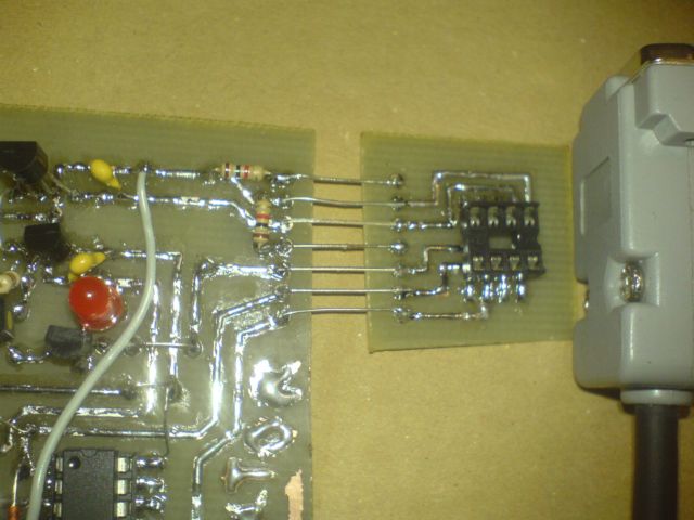
Пример печатной платы:
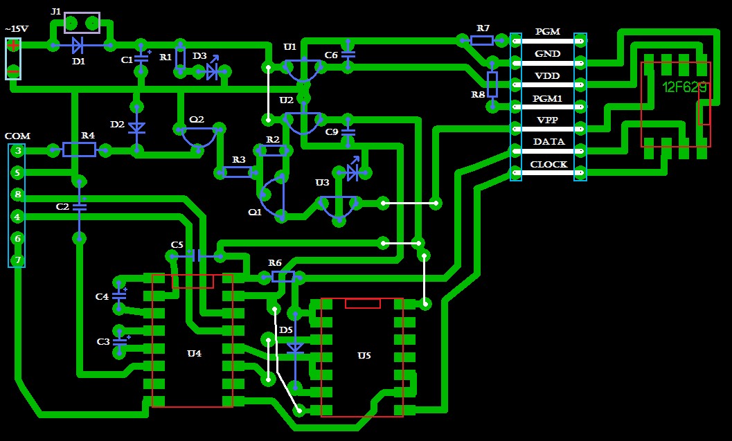
Скачать в формате .LAY можно тут СКАЧАТЬ
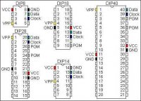
Как видно на картинке к пограмматору подключена панелька DIP8, для контроллеров PIC с 8 ног! Другие контроллеры (18 ног и 28 ног) подключаются аналогично, ниже представлены платы для этих контроллеров!
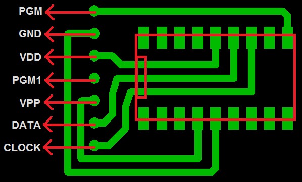
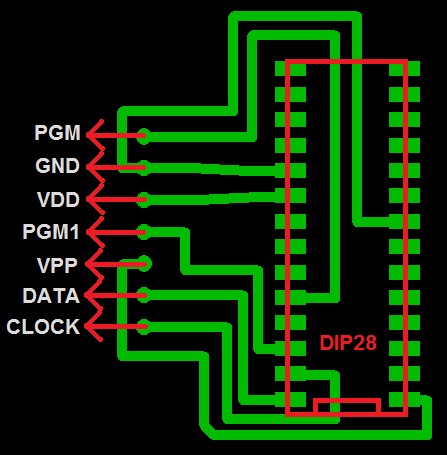
СКАЧАТЬ
Эти платы подключаются место панэльки DIP8
Таким образом вы можете подключить абсолютно любой тип PIC контроллер, посто соеденяя определенные контакты контроллера с програматором!
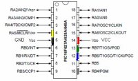
Ниже представлено расположение выводов разных PIC контроллеров!
Я попробовал собрать тэстувую плату для программатора, как выяснилось — программатор работает ЗАМЕЧАЕЛЬНО.
Фото тестовой конструкции:
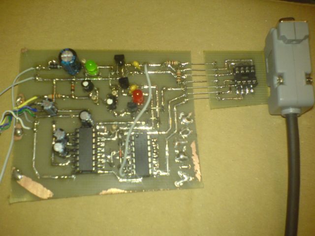
На качество платы внимания не обращаем, это был тэстовый вариант, для проверки программатора! Более качественная плата был сделана сразу после проверки!
.
Теперь самое главное , ПРООГРАММА ДЛЯ ПРОШИВКИ!
Самый лучший вариант — программа ICPROG! качаем её у нас СКАЧАТЬ или с официального сайта www.ic-prog.com
Вид программы:
Установка и настройка программы IC-PROG:
Распакуйте программу в отдельный каталог. В образовавшемся каталое должны находиться три файла:
icprog.exe — файл оболочки программатора.
icprog.sys — драйвер, необходимый для работы под Windows NT, 2000, XP. Этот файл всегда должен находиться в каталоге программы.
icprog.chm — файл помощи (Help file).
Для Windows XP:
Правой кнопкой щёлкните на файле icprog.exe. «Свойства» >> вкладка «Совместимость» >> Установите «галочку» на «Запустить программу в режиме совместимости с:» >>
выберите «Windows 2000«.
Запустите файл icprog.exe. Выберите «Settings» >> «Options» >> вкладку «Language» >> установите язык «Russian» и нажмите «Ok«.
Согласитесь с утверждением «You need to restart IC-Prog now» (нажмите «Ok«). Оболочка программатора перезапустится.
Настройки программатора:
Далее, «Настройки» >> «Опции» >> выберите вкладку «Общие» >> установите «галочку» на пункте «Вкл. NT/2000/XP драйвер» >> Нажмите «Ok» >> если драйвер до этого не был устновлен на вашей системе, в появившемся окне «Confirm» нажмите «Ok» . Драйвер установится, и оболочка программатора перезапустится.
Примечание:
Для очень «быстрых» компьютеров возможно потребуется увеличить параметр «Задержка Ввода/Вывода«. Увеличение этого параметра увеличивает надёжность программирования, однако, увеличивается и время, затрачиваемое на программирование микросхемы.
«Настройки» >> «Опции» >> выберите вкладку «I2C» >> установите «галочки» на пунктах: «Включить MCLR как VCC» и «Включить запись блоками«. Нажмите «Ok«.
«Настройки» >> «Опции» >> выберите вкладку «Программирование» >> снимите «галочку» с пункта: «Проверка после программирования» и установите «галочку» на пункте «Проверка при программировании«. Нажмите «Ok«.
Программа готова к работе.
Всё, можем смело программировать свой контроллер!
При возникновении ошибок или каких нибуть неполадок — поверте правильность изготовления платы и настроек программы!
Данный программатор был проверен мною не раз, за всё время небыло замечено не единой неполадки.
Прошивка PIC
 Nikolai4
Drayv
Nikolai4
Прикрепленные файлы
Дрич
goda
Дрич,если как здесьэто автор показал исходный код программы,она может быть написана на разных языкак програмирования асемблере,си,паскале и.т.д.
Для того чтобы получить файл прошивки который понимает м.к. с расширением HEX, исходный код нужно компилировать.Обычно это делают в той программе на которой пишут.
А если примерно в таком виде (шеснадцатиричном)
:020000040000FA
:1000000085EF07F01200FFFF04EF10F01200FFFF72
:10001000FFFFFFFFFFFFFFFF0CEF10F01200FFFFDD
:10002000FF FFFFFFFFFFFFFFFFFF00000401105174
:10003000600BE842E842E842E842E842000901E099
:1000400055D01151070A51E00B0A4FE0070A40E072
:10005000010A2CE 00B0A28E0020A26E0030A22E04B
:10006000080A12E0010A0EE00F0A0AE0030A01E0A2
:100070003CD00001010EB06F0001040EB76F36D006
:1000800036D834D090D8 32D00001010EB06F0001C4
:10009000B90EB16F000EB26F0001B8930001010EEE
:1000A000B56F24D0A8D822D0F5D820D00001010EF9
:1000B000B06F040114510001B 16FB26BBA0EB127D9
:1000C000000EB2230001B8930001010EB56F0ED0EF
:1000D0000001010EB06F04011451EA6ABA0FE96E13
:1000E000000EEA2212C4EFFF01D000 D01200800EF1
:1000F0000401105D57E11351030A34E0010A10E0D6
:10010000030A01E04DD00001010EB06F0001600E46
:10011000B16F0C0EB26F120E0001B56FB66 B40D00E
:100120000001010EB06F04011251F66EF76AD8900B
:10013000F636F7369E0EF6260D0EF7220900F5CF9D
:10014000B1F00A00F5CFB2F0020E0001F76AB125 56
:10015000F66EB251F7220900F5CFB5F00A00F5CFDF
:10016000B6F01ED00001010EB06F04011251F66E00
:10017000F76AD890F636F736A20EF6260D0EF7225D
: 100180000900F5CFB1F00A00F5CFB2F0B1C0F6FF2B
:10019000B2C0F7FF0800F5500001B56FB66B00D094
:1001A0000001B88312000001010EB06F0F0EE66E61
:1001B 000710EE66E0F0EE66E1BEC06F0E552E55290
:1001C000E552010EE66EBA0EE66E000EE66E1BEC10
:1001D00006F0E552E552E55212C4B9F0040112519D
:1001E00004 E10001050EB76F05D00001060EB76FE0
:1001F000E7EC04F012000401186B196B04011051B4
как правило это текстовый документ (блокнот) ,то достаточно сохранить этот файл с расширением HEX и все.
Arduino программатор PIC-ов.
Иногда встречаются очень интересные проекты выполненные на микросхемах PIC. Это микроконтроллеры с RISC архитектурой,
производимые фирмой Microchip Technology. Программаторы для PIC сложные и дорогие. Чтобы сделать программатор для PIC, нужен программатор для PIC, замкнутый круг для самодельщина. Но у нас есть Arduina! Сделаем из ардуины очень дешевый, очень простой, но работающий как очень дорогие HVSP программаторы микроконтроллеров от Microchip Technology.
HVSP — это High Voltage Serial Programming, высоковольтное последовательное программирование. Высоковольтное программирование позволяет сделать рабочим окирпиченный PIC контроллер из за неправильно выставленных фьюзов или заблокированных ног используемых при низковольтном программировании. В общем без разницы в каком состоянии Вам пришлют хитрые китайцы микроконтроллер, главное, чтобы он был аппаратно живой. А разлочить можно и ардуиной. Запрограммировать можно и ардуиной.
Схема. 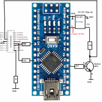
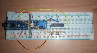
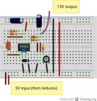
Сборка на макетной плате.
Настройка Step-UP DC-DC 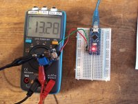
Пример работы программатора сделанного из ардуино нано в макете с парой дополнительных деталей которые можно выдрать из старой техники. Единственное для удобства я использовал повышающий преобразователь для получения 13V нужных для высоковольтного программирования. Удобство заключается в том, что просто вставляете программатор в USB и работаете не заморачиваясь на необходимости подачи внешнего питания. Иначе просто можно подать это напряжение от внешнего блока питания и схема станет еще проще.
Вложения
Комментарии
ТехнарьКто
AlexIz
Во как. Было такое подозрение. Сейчас попробую навесным монтажем сделать.
Кстати, в какой-то момент чип прочитался, но не стирался. Причём несколько раз программа показывала разные модели контроллеров. Чудеса.
SieOK
AlexGyver nRF24L01
Когда залез на сайт автора, немножко прозрел, занёс в закладки, и вот наконец-то то что надо. Зарегистрировался.
———————
Предыстория такова — понадобилось разово запрограммировать парочку PIC16F676, есть уже интересный проект паяльной станции, готовы печатные платы, всё собрано, даже собран программатор https://drive.google.com/file/d/1R0hs2tJRL9UQa5GvN7LYhbGIbJkaDu7T/view?usp=sharing
Работая с проектами на ардуино всё просто, так же казалось и с PIC, но не тут то было
Оказывается в PIC-контроллер можно заливать прошивку четырьмя способами: https://radiohlam.ru/progr_asm_6/
Более того для полного понимания прошивки разных МК нужно знать отличие между ними. Очень хорошая ссылка на сводную таблицу для того чтобы быстро разобраться почему программатор заливает прошивку в один контроллер, и не заливает в другой (плюс там ещё и распиновки из даташитов даны) https://radiohlam.ru/pic_param/
Результатом анализа разных схем программаторов ( а хотелось попроще и поуниверсальней ) стала сводная таблица в картинке:
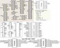
и несколько схемных решений:
1 — Программатор ART2003 от LPT-порта: 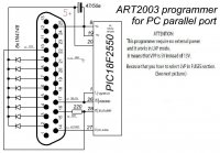
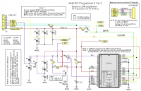
2 — Multi PIC Programmer 5 ver.2 с какого-то японского сайта:
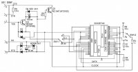
3 — Упрощенная схема Multi PIC Programmer (Источник: Радиоаматор №9, 2014 ) :
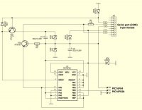
4 — Классический JDM-программатор без поддержки VPP:
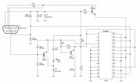
5 — Классический JDM-программатор c поддержкой VPP:
Но контроллер PIC16F676 так запрограммирован и не был.
Пробовал заливать прошивку программами IC-Prog_v-1.05, IC-Prog_v-1.06, WinPic800, PicPGM, WinPICpgm, затёр даже калибровочную константу, пришлось купить ещё один контроллер в этом же магазине из этой же партии.
Результат всех моих усилий в виде архива (дистрибутивы программ, собранные и отредактированные материалы, сводная таблица для локального просмотра) можно взять на гуглодиске, может кому пригодится:
ПРОСТЫЕ__PIC-AVR.rar
 drive.google.com
SieOK
У кого нет повышающего DC-DC использованного в статье, его легко сделать самому из копеечных деталей:
— Схема преобразователя 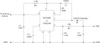
— Схема регулировки VPP:
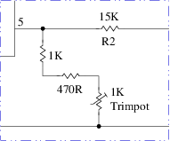
— Вид макетной сборки :
AlexIz
ТехнарьКто
Что значит тоже? У меня все замечательно работает, даже на такой макетке. Но для макетной платы пришлось на плате ардуино нано убрать все неиспользуемые в схеме штыри. Менять скетч как предлагает DAK я просто не пробовал. Ардуина должна быть 5-ти вольтовая 16Mhz.
Konstantin900
Что значит тоже? У меня все замечательно работает, даже на такой макетке. Но для макетной платы пришлось на плате ардуино нано убрать все неиспользуемые в схеме штыри. Менять скетч как предлагает DAK я просто не пробовал. Ардуина должна быть 5-ти вольтовая 16Mhz.
PIC какой прошивать пытаетесь? Я не экстрасенс. Есть PIC контроллеры с однократной возможностью записи. Есть PIC контроллеры не поддерживаемые этим программатором. Вариантов сделать из рабочей конструкции кирпич, очень много. Питание подавать только со вставленным в схему PIC-ом. Питание подавать сразу два, 5 вольт и 13 вольт одновременно. Питание 13 вольт на PIC подавать только через токоограничительный резистор, на схеме 10 КОм. Питание 5 вольт на PIC контроллер подавать одновременно с питанием на ардуино программатор. Если с азов то сначала надо установить драйвер для платы ардуино. Из Arduino IDE в ардуину используемую как программатор должны прошиваться скетчи. Если не прошивается — разбирайтесь, это азы. Ардуина программатор с неправильно подключенным или совсем не подключенным PIC-ом работать не будет. Нет PIC нечего прошивать, стираться и прошиватся естественно не будет. Прошитый как программатор ардуино с предварительно подключенным PIC-ом для прошивки. Подать питающие напряжения, если 5V от USB, а 13 вольт со стороны то сначала подать 13 вольт поскольку это важно для перевода PIC в режим программирования. Включить программатор в USB. Запустить программу ArdPicProgHost. Выбрать в программе Номер com порта программатора ардуино. Если порт выбран, просто навести на это окошко указатель мышки и нажать левую кнопку мыши. Подождать когда окно выбора порта сменит цвет на зеленый. Выгрузить ArdPicProgHost нажав мышкой на крест в углу окна программы. Снова запустить ArdPicProgHost. При всем этом программатор из USB не вытаскивать, как вначале включили, так и не трогать. В ArdPicProgHost запущенный второй раз навести на окошко выбора порта указатель мышки и нажать левую кнопку мыши. Подождать когда окно выбора порта сменит цвет на зеленый. И только теперь в программе правильно определиться тип подключенного PIC контроллера если подключение выполнено правильно и подключен поддерживаемый скетчем PIC. Это "pic12f629, pic12f675, pic16f630, pic16f676, pic16f84, pic16f84a, pic16f87, pic16f88, pic16f627, pic16f627a, pic16f628, pic16f628a, pic16f648a, pic16f882, pic16f883, pic16f884, pic16f886, pic16f887".
Другие PIC тоже можно подключить если внести изменения в скетч. Поскольку скетч и программа разработаны другими людьми, а предоставленный функционал меня устраивает, скетч и ArdPicProgHost приведены здесь в том виде, котором их выложили авторы.
Чем смог, надеюсь помог.