
Lesson 1: Intro to the ESP32
Image from makeradvisor.com. There are literally dozens of ESP32 boards. Search online for comparisons (e.g., link).
The ESP32 is a low-cost, “system-on-a-chip” board with integrated WiFi, Bluetooth, and a Tensilica Xtensa LX6 microprocessor running at 160 or 240 MHz. It is a successor to the massively successful ESP8266. The ESP32 is far more powerful than introductory Arduino boards like the Uno or Leonardo but also more complex.
There are literally dozens of ESP32 boards on the market, including Adafruit’s Huzzah32 and Sparkfun’s ESP32 Thing. Search online for comparisons (e.g., link). We will be using the Huzzah32.
Programming environment
You can program the ESP32 in variety of languages and programming environments, including C/C++ , Micropython, Lua, and more. For programming environments, you can use Espressif’s IoT Development Framework (IDF) or VSCode with PlatformIO. Many ESP32 boards have Arduino libraries so you can also use the Arduino IDE, which is what we will do. This greatly simplifies programming the ESP32 (but at a cost of flexibility and efficiency).
The Adafruit ESP32 Huzzah32 Feather
For our course, we will be using Adafruit’s Huzzah32 ESP32 Feather Board, which came out in May 2017. This board is built on Espressif’s ESP32 WROOM module. While a bit more expensive than other ESP32 boards, Adafruit produces reliable, high-quality products and has good customer support (check out the Adafruit forums). In addition, because the Huzzah32 is a “Feather” board, it’s compatible with Adafruit’s expansion board series called Wings (link1, link2).
The Huzzah32 Specs
| Name | Arduino Uno | Huzzah32 |
|---|---|---|
| Image | 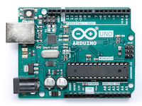 |
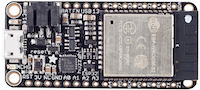 |
| Microcontroller | 8-bit, 16 MHz ATmega328P | 32-bit, 240 MHz dual core Tensilica LX6 |
| Microcontroller Manufacturer | Microchip (Atmel) | Espressif |
| System-on-a-chip | N/A | ESP32 |
| Input voltage (limit) | 6-20V | Use either USB (5V) or LiPoly (3.7/4.2V) |
| Operating voltage | 5V | 3.3V |
| Flash memory | 32KB (0.5KB used by bootloader) | 4MB |
| SRAM | 2KB | 520KB |
| GPIO pins | 14 | 21 |
| PWM pins | 6 | All |
| Analog inputs | 6 | 14 |
| Wi-Fi | N/A | 802.11b/g/n HT40 Wi-Fi transceiver |
| Bluetooth | N/A | Dual mode (classic and BLE) |
Recall that flash memory is where your compiled program is stored and SRAM is where your microcontroller creates and manipulates variables when it runs.
The ESP32 also has 2xI2S Audio, 2xDAC, 2xI2C (only one configured by default in the Feather Arduino IDE support), 3xSPI (only one configured by default in Feather IDE support). See Adafruit overview.
There is a hardware floating point unit (FPU) on ESP32; however, there have been some criticisms about its performance (link1, link2).
The Huzzah32 is not designed for external power supplies, so either use the USB port with a 5V 1A USB wall adapter or by plugging into your computer or a LiPoly battery (3.7/4.2V). Unlike with the Arduino Uno and Leonardo, do not use a 9V battery or you could damage your board!
ESP32 pin list
The official ESP32 pin list is here:
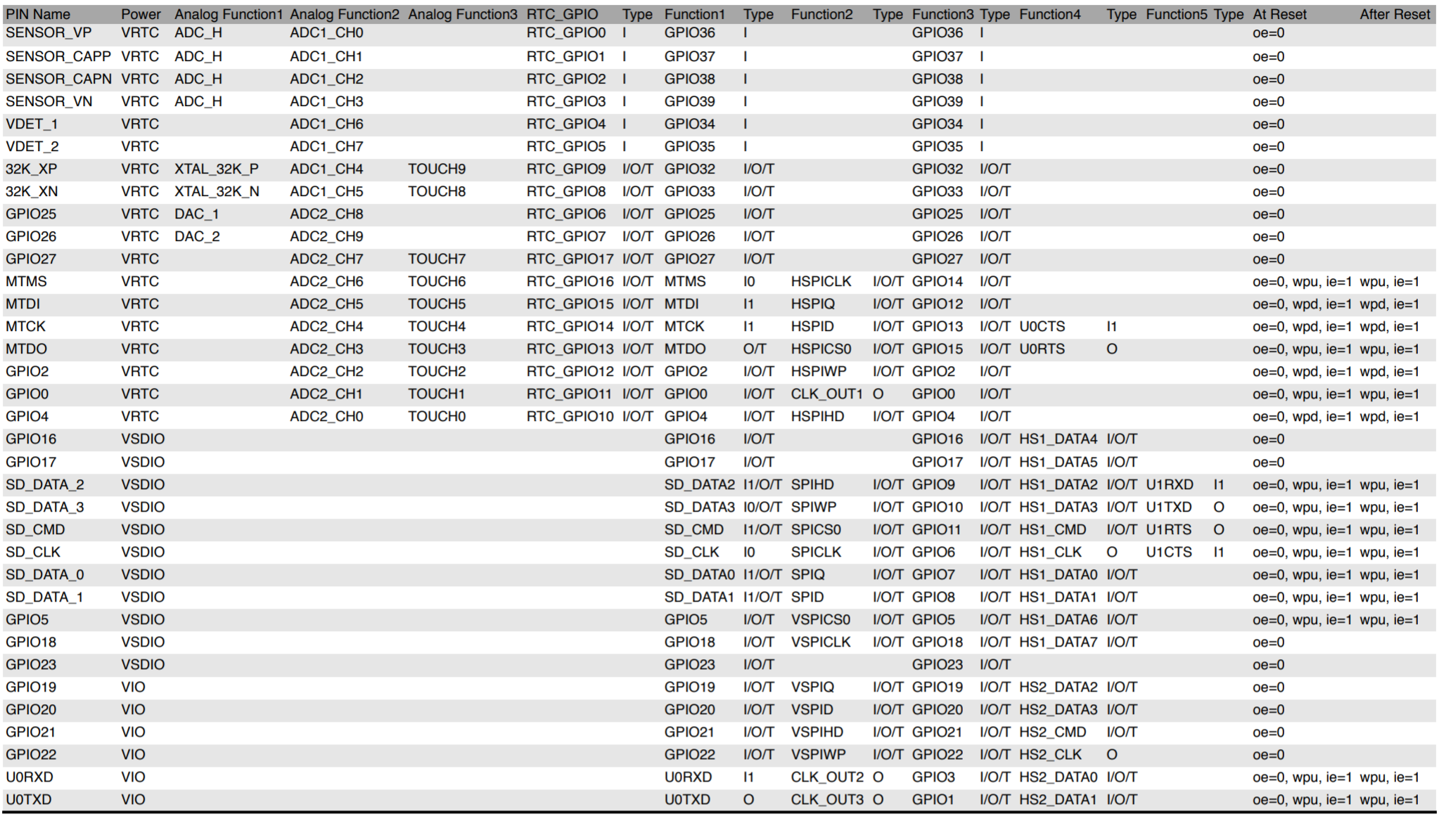 Screenshot of the ESP32 pin list PDF.
In our code, we will reference the pins based on their GPIO number, their analog input number (prefixed by ‘A’) for analog input, or their touch number (prefixed by ‘T’) for using capacitive touch sensing. We can always use the GPIO number, however (which is just an integer). The ESP32 datasheet often uses the pin name (far left column of the above pin list) to refer to pins.
Huzzah32 pin diagram
So, what do all of these pins do? Oh, so many things!
The pin diagram for the Huzzah32 in the official Adafruit docs is pretty confusing. So, we created our own:
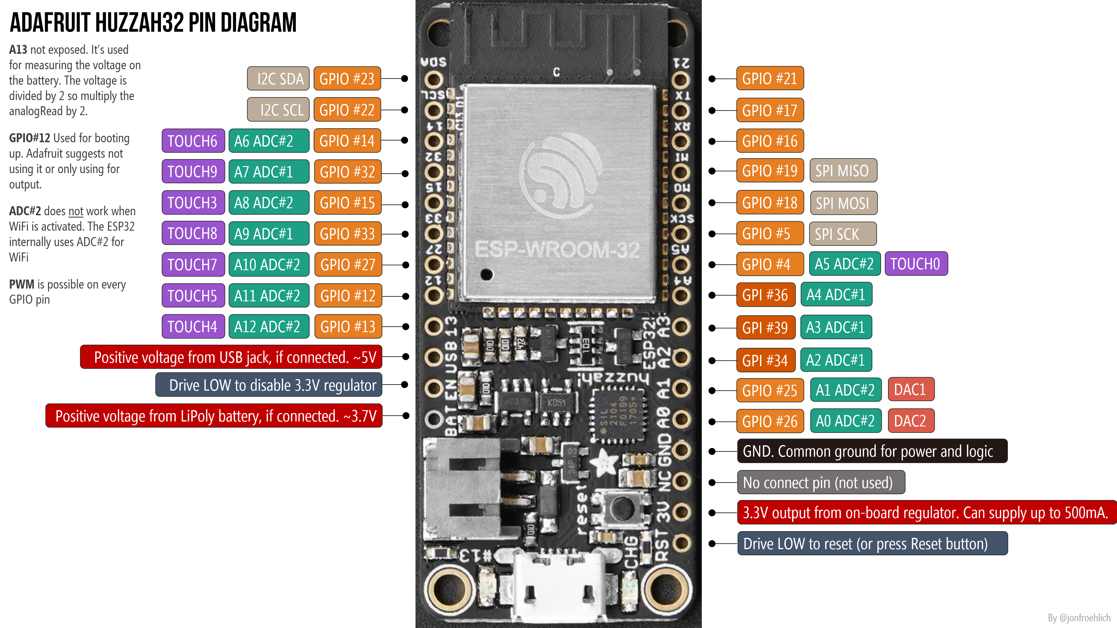 See the Adafruit Huzzah32 docs for details. Right-click and open image in a new tab to zoom in.
Important notes
- The ESP32 runs on 3.3V power and logic, and unless otherwise specified, GPIO pins are not 5V safe! The BAT pin should generally not be used directly as the Huzzah32 has a JST connection for the LiPoly battery. You should most definitely not hook up a 9V connection here.
- There are 21 GPIO pins; however, on the Huzzah32, pins 34 (A2), 39 (A3), 36 (A4) are not output-capable and thus should only be used for input. So, 18 GPIO pins in total. Be forewarned: the pins are in a strange order, so read the diagram carefully.
- PWM is possible on all 18 GPIO pins
- 14 of the 21 GPIO pins can be used analog input pins; however, A13 is not exposed. It’s used for measuring the voltage on the LiPoly battery via a voltage divider. When reading in the battery level using analogRead(A13) , make sure to multiply by 2 to get correct reading. Here’s an initial program to read and print out the battery level to Serial (link)
- The ADC resolution is 12 bits (0-4095). This is in contrast to the Arduino Uno and Leonardo, which uses ATmega chips with 10 bit ADCs (so, 0-1023). Make sure you use the proper max value in your conversions (e.g., using map() )
- GPIO 13 is the LED_BUILTIN (the red LED next to micro USB)
- The charging circuit light will flash quickly when there is no LiPoly battery plugged in. It’s harmless and doesn’t mean anything. This LED will also flash (more slowly) when the battery is plugged in and charging. The battery charges automatically when plugged in and the Huzzah32 is externally powered.
- Only power your Huzzah32 either using the USB plug (max 5V, 1A) or a LiPoly battery (3.7/4.2V)
The Huzzah32 has 21 GPIO pins; however pins 34 (A2), 39 (A3), 36 (A4) are not output-capable. In this animation, we are attempting to fade in/out all 21 GPIO pins and demonstrating that only 18 work for output.
ADC2 is only usable when WiFi not activated
The Adafruit docs state (somewhat confusingly) that ADC#1 only works when WiFi has started. We empirically tested this (see video below) and found this not to be true. On the other hand, the Espressif docs state that ADC#2 only works when WiFi has not started. We did find this to be true. So, we believe the Espressif docs are right and the Adafruit docs are wrong. Update: it turns out that the Adafruit docs are accurate but just poorly phrased. Indeed, ADC#1 is the only ADC that works when using WiFi (see Reddit post).
Indeed, we empirically tested this. Check out our two programs:
-
reads from all analog input pins and prints the values to Serial (so you can view them in Serial Console or Serial Plotter) extends AnalogInputTest but turns on WiFi.
In the following video, I’m using AnalogInputTest.ino to test all 13 analog input pins ( A0 — A12 ) using a trim potentiometer for input and the Serial Plotter for output.
Huzzah32 installation instructions for the Arduino IDE
Step 1: Add ESP32 to Arduino Board Manager
Open the Arduino IDE
Go to Preferences 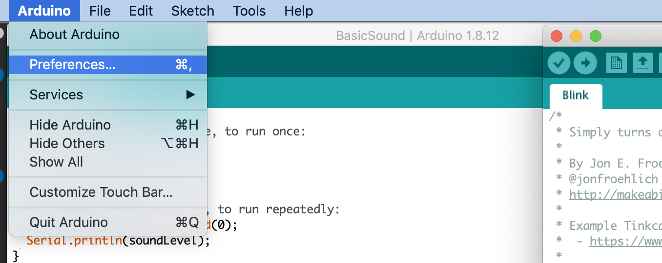
In preferences, find the Additional Board Manager URLs: field 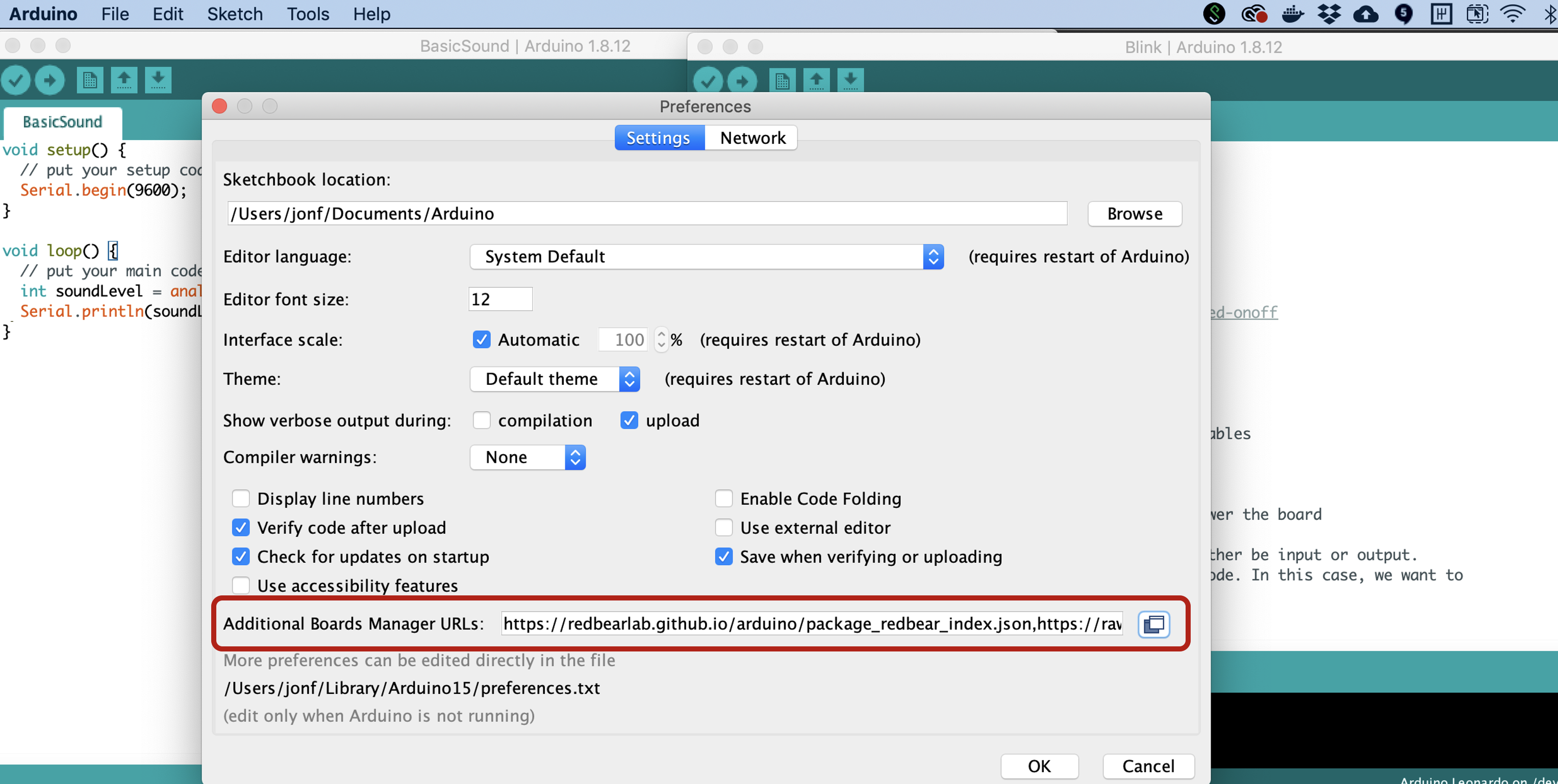
Add the ESP32 JSON url https://raw.githubusercontent.com/espressif/arduino-esp32/gh-pages/package_esp32_index.json 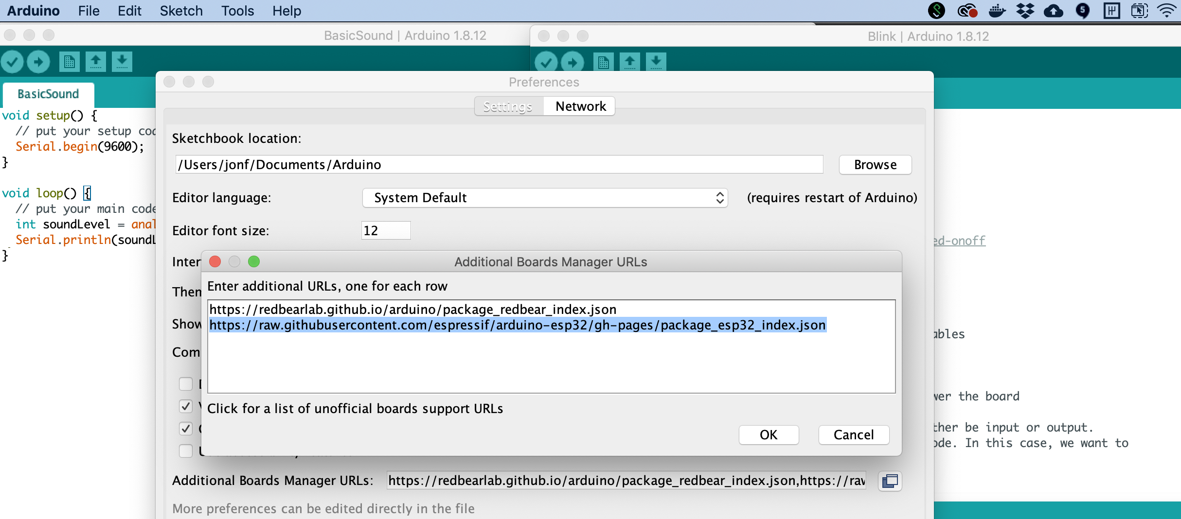
Open the Arduino IDE Board Manager 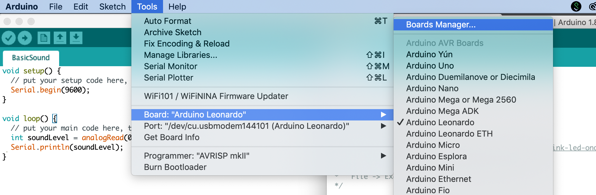
Search for ESP32 and click Install 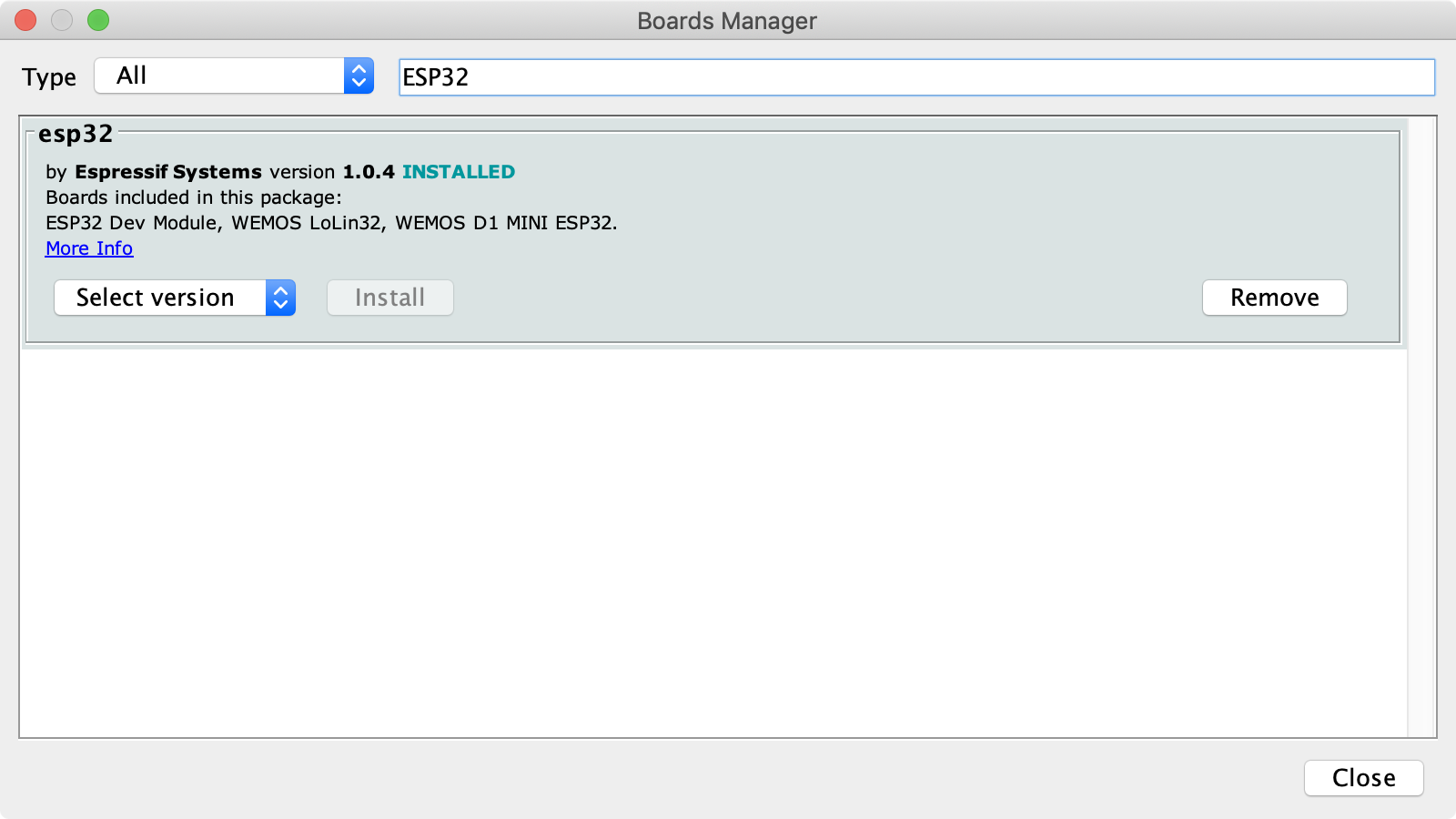
Step 2: Install USB to UART Bridge Virtual COM Port Driver
As noted in the official Adafruit Huzzah32 Arduino IDE installation instructions, the second step is to install the USB to UART Bridge Virtual COM Port (VCP) driver to interface with the ESP32 board. You can download the driver from Windows, Mac, and Linux here.
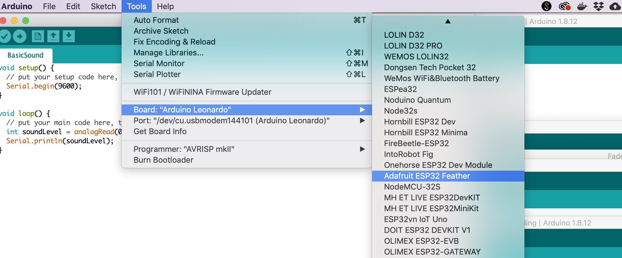
Step 3: Select “Adafruit ESP32 Feather” in board menu
Once installed, select the Adafruit ESP32 Feather in the Board menu.
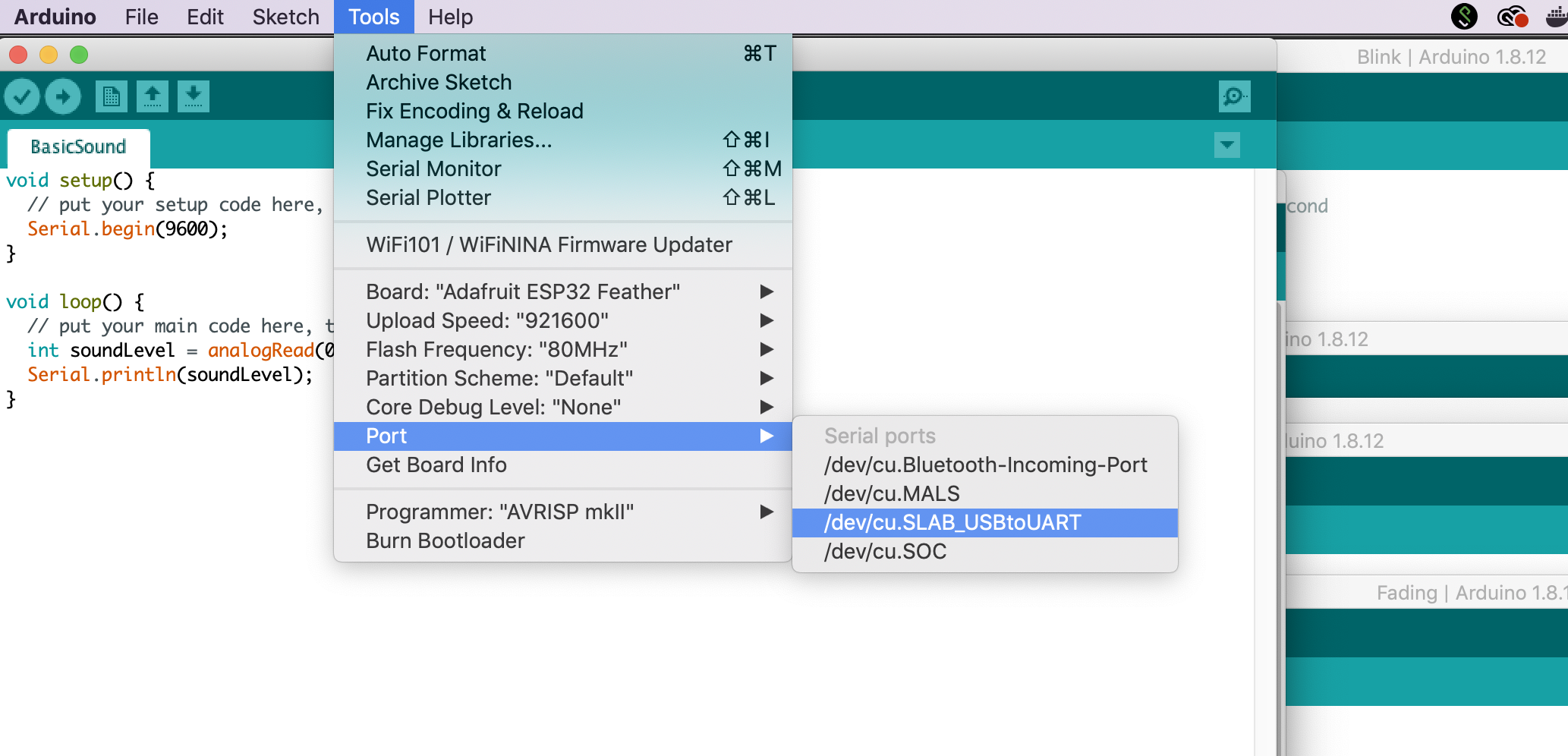
Step 4: Select the appropriate port
Finally, select the appropriate port
Resources
Official ESP32 Documentation
Other
-
. Written for Sparkfun’s ESP32 Thing board but has relevant WiFi and BLE examples.
Next Lesson
In the next lesson, you will write your first ESP32 program using the ESP32 Arduino library.
Espressif ESP32 Tutorial — Part 3

The native software development framework for the ESP-32 is called the Espressif IoT Development Framework (ESP-IDF). If you want maximum functionality and compatibility this is what you should use. It is a bit more “hard core” than some of the other programming options but it does help you better understand what is happening under the hood.
The ESP-IDF functionality includes menu based configuration, compiling and firmware download to ESP32 boards.
To develop applications for ESP32 you will need:
- A PC loaded with either Windows, Linux or the Mac operating system
- Toolchain to build the Application for ESP32
- ESP-IDF that essentially contains the API for ESP32 and scripts to operate the Toolchain
- A text editor to write programs (Projects) in C, e.g. Eclipse
- The ESP32 board itself and a USB cable to connect it to the PC
The quickest way to start development with the ESP32 is by installing a prebuilt toolchain. Head over to the Espressif site and follow the provided instructions for your OS. I will outline the process for Mac.
Install Prerequisites
The first thing you need to do is install pip.
Then install pyserial:
Tool Chain Setup
The ESP32 toolchain for macOS is available for download from the Espressif website.
Обзор, установка и программирование на ESP32

Интерес к интернету вещей растет с каждым днем, свои курсы по технологии IoT запустили и Cisco, и Samsung. Но большинство этих курсов базируются на собственном железе компаний, довольно дорогом, в то время как практически все то же самое можно сделать на гораздо более дешевом железе самостоятельно, получив при этом массу удовольствия и полезных навыков.
Какую плату выбрать?
Когда неофит от IoT полезет в интернет, одним из первых модулей, которые он найдет, будет ESP8266. И действительно, он обладает массой достоинств: дешевый, много различных плат на его основе, позволяющих использовать его как самостоятельное устройство и подключать к сложным Arduino-based проектам. Но ESP8266, выпущенный в 2014 году, довольно быстро перестал удовлетворять запросы пользователей, и в 2015 году компания-разработчик Espressif выпускает новый микроконтроллер — ESP32.

Различия между ESP8266 и ESP32
Точно так же, как и в случае с ESP8266, разработчики создали довольно много плат, базирующихся на новом микроконтроллере. В данной статье все примеры тестировались и проверялись на плате MH-ET LIVE ESP32 DevKit. Плата для обзора была любезно предоставлена интернет-магазином Amperkot.
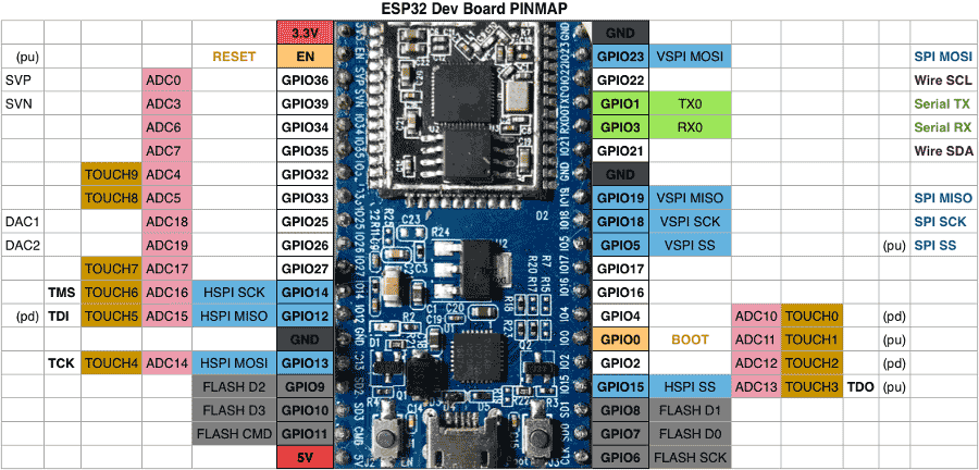
Pinoutmap платы
Начинаем программирование
Как и у любой платы, основанной на ESP32, у MH-ET LIVE ESP32 DevKit есть достаточно большой набор языков программирования. Во-первых, это Arduino C, во-вторых, Lua, а в-третьих и в-четвертых — MicroPython и Espruino. Про Espruino — сборку JS для программирования микроконтроллеров — уже рассказывалось, но в той статье разбиралась работа только на плате Espruino Pico, заточенной под Espruino.
К сожалению, портирование Espruino на ESP32 еще не до конца завершено. Часть возможностей, например обновление по воздуху и Bluetooth, недоступна. Но так как Espruino — open source проект, любой может добавить свою функциональность.
Установка
- Скачиваем на официальном сайте свежую сборку Espruino. А если не доверяешь готовым сборкам, то можно собрать прошивку самостоятельно:
Разработчики Espruino создали свою IDE, Espruino Web IDE. Эта программа распространяется через Chrome Web Store, также существуют нативные приложения для Windows (32 и 64).
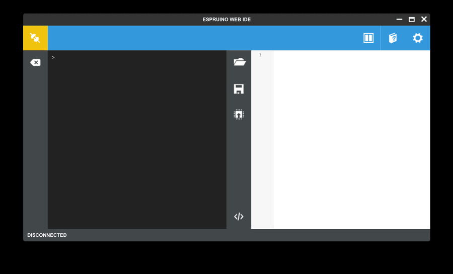
Espruino Web IDE
Перед первым запуском нужно залезть в настройки, вкладка COMMUNICATIONS, и убедиться, что скорость общения выставлена на 115200, а также изменить поле Save on Send с No на Yes, иначе все программы после перезапуска слетят.
Теперь достаточно запустить IDE, подключиться к плате и набрать в консоли 1 + 2 : если ты получил 3 , значит, все настроено правильно и можно начинать полноценную работу.
Hello world
Во всех языках программирования, предназначенных или модифицированных для программирования микроконтроллеров, самая простая программа — так называемый Blink , мигание встроенным светодиодом. Но это как-то скучно. Поэтому нашей первой программой станет программа для управления светодиодом с помощью веб-страницы. И действительно, JS — это же язык веба.
Можно заметить, что синтаксис практически ничем не отличается от обычного JS. Давай разбираться, что же происходит в этой программе.
- var wifi = require(«Wifi») — для начала мы подгрузили необходимый нам модуль для работы с Wi-Fi. Логично будет задаться вопросом: а откуда мы его взяли? Допустим, есть встроенные в прошивку модули. А если нам нужно загрузить с какого-нибудь внешнего сайта? Функция require поддерживает синтаксис вида require(«https://github.com/espruino/EspruinoDocs/blob/master/devices/PCD8544.js»);, а WebIDE для поиска модулей онлайн, по умолчанию используется https://www.espruino.com/modules.
- Следующий блок кода отвечает за поднятие точки доступа с именем EspruinoAP и паролем 0123456789. В случае успешного запуска в консоль выводится соответствующее сообщение.
- Функция onPageRequest — собственно сам веб-сервер. В этой функции разбирается адрес и проверяется, что нужно сделать, в зависимости от запроса:
- если загружается первая страница — /, то вернуть 200-й заголовок и сообщение типа text/html «Hello, ][aker!», в обрамлении HTML-тегов;
- если загружается страница включения — /on, то вернуть200-й заголовок и сообщение Enable, а также включить светодиод. Заметим, что используется привычная Arduin’щикам функция digitalWrite(pin, value);
- небольшое отличие в случае страницы выключения —/off, для выключения светодиода используется не функция digitalWrite(pin, value), а метод write(value);
во всех остальных случаях возвращаем ошибку «404 — Page Not Found».
Важно заметить, что мы можем возвращать различный контент: обычный текст, HTML, XML и так далее.
RGB-лампочка, управляемая по MQTT
Очень часто создание своего умного дома начинается именно с подсветки. Но просто включать/выключать светодиодную лампу — это банально. Для освещения небольших помещений, а также для украшения и создания праздничной атмосферы нередко используются адресные RGB-светодиоды. Воспользуемся ими и мы. В качестве MQTT-брокера и клиента возьмем Adafruit IO.
Из стандартных виджетов нам понадобятся всего два: Toggle и Color Picker.
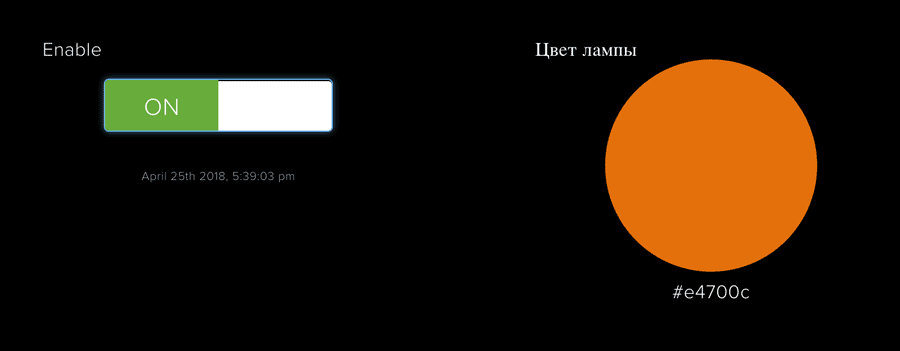
Adafruit IO Dashboard
Приступим к разбору программы.
- Для начала объявляем переменные, необходимые для подключения к Wi-Fi, а также количество светодиодов и пин, к которому они подключены.
- Функция colorall(color,count,pin) отвечает за одновременное окрашивание всех светодиодов в один цвет. Для этого следует создать массив, в который count раззаписать по очереди три составляющих цвета. То есть для окрашивания двух светодиодов в синий цвет массив должен быть такой: [0,0,255,0,0,255]. Как можно заметить, в этой функции подключается предзагруженная библиотека neopixel. И еще один интересный факт: здесь перепутан порядок цветов — не RGB, а GRB. Это очень странно, но так есть.
- Следующие четыре функции нужны для перевода цвета из шестнадцатеричной записи в RGB. Они нам понадобятся, ведь Color Picker отправляет цвет как строку вида #RRGGBB.
- Подключаемся к Wi-Fi, в случае успешного подключения в лог выведется сообщение.
- Теперь необходимо подключиться к MQTT-брокеру. В первый раз, когда попробуешь запустить, интерпретатор может выдать ошибку, что такая библиотека не найдена. На самом устройстве ее действительно нет, она подгружается из интернета, поэтому, если подключение к интернету не удалось, она не сможет скачаться. Подожди, пока установится стабильное подключение, и перезагрузи устройство.
- Теперь надо описать функциональность клиента. У MQTT-клиента есть различные события, на которые можно (и нужно) повесить обработчики.
- Когда соединение установлено (connected), надо подписаться (mqtt.subscribe(topic)) на необходимые топики: один соответствует переключателю, другой — Color Picker’у. И для удобства выведем в консоль сообщение об успешном подключении.
- Теперь надо прописать, что необходимо делать при появлении в том или ином топике какого-либо сообщения (publish). Для начала выведем имя топика и текст сообщения.
- Переключатель может возвращать всего два сообщения: OFF или ON. Логично, что при получении первого сообщения необходимо выключить все светодиоды, а вот что делать при включении — остается на выбор программиста. Я решил зажечь все светодиоды белым цветом, с 50%-й яркостью.
- Если же пользователь изменяет цвет, то мы переводим цвет в RGB, точнее в GRB-запись и записываем этот цвет во все светодиоды.
MQTT-сервисы
Кроме Adafruit IO, есть и другие MQTT-сервисы, с похожей функциональностью. Если говорить про полностью «ручное» управление — первым на ум приходит Eclipse Mosquitto. Этот брокер можно установить на домашний компьютер или на Raspberry Pi и при помощи встроенных утилит mosquitto_sub и mosquitto_sub вручную (или используя Python) создавать топики, подписываться на них, отправлять сообщения.
В Arduino-кругах очень популярен сервис Blynk. У этого сервиса есть библиотеки для Arduino, клиенты под iOS и Android, а также его сервер распространяется через GitHub и может быть поднят на любом компьютере. Есть небольшой нюанс: каждый виджет, добавляемый на панель приложения, «стоит» определенное количество внутренних единиц. Изначального баланса хватит на большинство приложений, но если тебе захочется сделать полноценную программу и выложить ее в App Store / Play Market (а Blynk и такое позволяет), то придется раскошелиться.
Кроме этого, и в App Store, и в Play Market наберется достаточно много клиентских приложений, а в интернете есть масса MQTT-брокеров. Например, CloudMQTT. У него доступен бесплатный тариф — самое то для начала.
Система контроля состояния комнаты
Представим, что у нас есть комната, в ней ряд датчиков и нам нужно следить, все ли там в порядке. Постоянно смотреть за показателями надоест довольно быстро, поэтому нам требуется, чтобы в определенных случаях включался свет, причем не какой-то светодиод, а полноценная лампа. А всю информацию будем отправлять опять же на Adafruit IO.
Датчики у нас следующие:
- датчик уровня воды — аналоговый;
- датчик температуры и влажности DHT11 — цифровой;
- датчик звука — цифровой.
Кроме этого, для управления светом нам понадобится реле.

Схема подключения
В данной программе нам опять понадобится подключение к Wi-Fi и MQTT-брокеру. Они аналогичны первой программе, единственное отличие — MQTT-клиент при подключении не подписывается ни на какие топики.
В начале объявим, какие пины для чего мы будем использовать. И если первый пример теоретически мог бы быть запущен на ESP8266, то этот пример требует только ESP32, ведь нам нужно уже два аналоговых пина.
Для датчика температуры и влажности существует собственная библиотека, которую необходимо подключить: require(«DHT11»).
Реле управляется обычным изменением данных на цифровом пине. 0 — реле выключено, 1 — включено. Таким образом, подключая лампы, удлинители и прочие устройства через реле, ими можно управлять через интернет. Это один из самых частых IoT-приемов.
Но самое интересное — это, конечно, функция setInterval(function,time). Всем, кто писал на Arduino C, известна основная функция void Loop()<> — это функция, которая постоянно вызывается после загрузки программ. Так вот, setInterval гораздо круче. Во-первых, можно (и нужно) задать время повтора в миллисекундах, а во-вторых, можно задавать вызовы нескольких функций, причем с разной частотой.
Еще из интересных нюансов у меня есть переменные SoundLevel и Waterlevel, поскольку и датчик уровня воды, и датчик звука — аналоговые, показания на разных платах могут различаться и необходимо провести калибровку. На датчике звука установлен потенциометр, для регулировки чувствительности.
Кроме этого, в данном скрипте появился вызов функции mqtt.publish(field,data), он отправляет значение поля data в заданный канал на MQTT-брокере.

SmartRoom Dashboard
Заключение
Примеры, разобранные в данной статье, призваны продемонстрировать, что в создании собственных IoT-девайсов нет ничего сложного. Действительно, JS, на котором базируется Espruino, довольно несложный ЯП, а количество уроков по нему в интернете зашкаливает. В начале статьи я писал, что самостоятельная разработка дешевле, чем покупное устройство. В качестве примера, подтверждающего это, скажу, что одна розетка, управляемая по Wi-Fi, стоит в среднем примерно в два раза больше платы, используемой в обзоре, и в 10–20 раз больше, чем реле, необходимое для управления обычной розеткой. Выводы делай сам.
Get Started
This document is intended to help you set up the software development environment for the hardware based on the ESP32 chip by Espressif. After that, a simple example will show you how to use ESP-IDF (Espressif IoT Development Framework) for menu configuration, then for building and flashing firmware onto an ESP32 board.
This is documentation for stable version v4.4 of ESP-IDF. Other ESP-IDF Versions are also available.
Introduction
ESP32 is a system on a chip that integrates the following features:
Wi-Fi (2.4 GHz band)
Dual high performance Xtensa® 32-bit LX6 CPU cores
Ultra Low Power co-processor
Powered by 40 nm technology, ESP32 provides a robust, highly integrated platform, which helps meet the continuous demands for efficient power usage, compact design, security, high performance, and reliability.
Espressif provides basic hardware and software resources to help application developers realize their ideas using the ESP32 series hardware. The software development framework by Espressif is intended for development of Internet-of-Things (IoT) applications with Wi-Fi, Bluetooth, power management and several other system features.
What You Need
An ESP32 board
USB cable — USB A / micro USB B
Computer running Windows, Linux, or macOS
You have a choice to either download and install the following software manually
-
Toolchain to compile code for ESP32
-
Build tools — CMake and Ninja to build a full Application for ESP32
-
ESP-IDF that essentially contains API (software libraries and source code) for ESP32 and scripts to operate the Toolchain
or get through the onboarding process using the following official plugins for integrated development environments (IDE) described in separate documents
-
Eclipse Plugin (installation link)
-
VS Code Extension (setup)
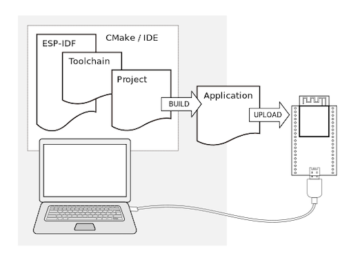
Development of applications for ESP32 
Development Board Overviews
If you have one of ESP32 development boards listed below, you can click on the link to learn more about its hardware.
Installation Step by Step
This is a detailed roadmap to walk you through the installation process.
Setting up Development Environment
Creating Your First Project
Step 1. Install prerequisites
Some tools need to be installed on the computer before proceeding to the next steps. Follow the links below for the instructions for your OS:
This guide uses the directory
/esp on Linux and macOS or %userprofile%\esp on Windows as an installation folder for ESP-IDF. You can use any directory, but you will need to adjust paths for the commands respectively. Keep in mind that ESP-IDF does not support spaces in paths.
Step 2. Get ESP-IDF
To build applications for the ESP32, you need the software libraries provided by Espressif in ESP-IDF repository.
To get ESP-IDF, navigate to your installation directory and clone the repository with git clone , following instructions below specific to your operating system.
Linux and macOS
Open Terminal, and run the following commands:
ESP-IDF will be downloaded into
Consult ESP-IDF Versions for information about which ESP-IDF version to use in a given situation.
Windows
In addition to installing the tools, ESP-IDF Tools Installer for Windows introduced in Step 1 can also download a copy of ESP-IDF.
Consult ESP-IDF Versions for information about which ESP-IDF version to use in a given situation.
If you wish to download ESP-IDF without the help of ESP-IDF Tools Installer, refer to these instructions .
Step 3. Set up the tools
Aside from the ESP-IDF, you also need to install the tools used by ESP-IDF, such as the compiler, debugger, Python packages, etc.
Windows
ESP-IDF Tools Installer for Windows introduced in Step 1 installs all the required tools.
If you want to install the tools without the help of ESP-IDF Tools Installer, open the Command Prompt and follow these steps:
or with Windows PowerShell
Linux and macOS
or with Fish shell
To install tools for multiple targets you can specify those targets at once. For example: ./install.sh esp32,esp32c3,esp32s3 . To install tools for all supported targets, run the script without specifying targets ./install.sh or use ./install.sh all .
Alternative File Downloads
The tools installer downloads a number of files attached to GitHub Releases. If accessing GitHub is slow then it is possible to set an environment variable to prefer Espressif’s download server for GitHub asset downloads.
This setting only controls individual tools downloaded from GitHub releases, it doesn’t change the URLs used to access any Git repositories.
Windows
To prefer the Espressif download server when running the ESP-IDF Tools Installer, mark the Use Espressif download mirror instead of GitHub in the screen Select Components section Optimization.
Linux and macOS
To prefer the Espressif download server when installing tools, use the following sequence of commands when running install.sh :
Customizing the tools installation path
The scripts introduced in this step install compilation tools required by ESP-IDF inside the user home directory: $HOME/.espressif on Linux and macOS, %USERPROFILE%\.espressif on Windows. If you wish to install the tools into a different directory, set the environment variable IDF_TOOLS_PATH before running the installation scripts. Make sure that your user account has sufficient permissions to read and write this path.
If changing the IDF_TOOLS_PATH , make sure it is set to the same value every time the Install script ( install.bat , install.ps1 or install.sh ) and an Export script ( export.bat , export.ps1 or export.sh ) are executed.
Step 4. Set up the environment variables
The installed tools are not yet added to the PATH environment variable. To make the tools usable from the command line, some environment variables must be set. ESP-IDF provides another script which does that.
Windows
ESP-IDF Tools Installer for Windows creates an “ESP-IDF Command Prompt” shortcut in the Start Menu. This shortcut opens the Command Prompt and sets up all the required environment variables. You can open this shortcut and proceed to the next step.
Alternatively, if you want to use ESP-IDF in an existing Command Prompt window, you can run:
or with Windows PowerShell
Linux and macOS
In the terminal where you are going to use ESP-IDF, run:
or for fish (supported only since fish version 3.0.0):
Note the space between the leading dot and the path!
If you plan to use esp-idf frequently, you can create an alias for executing export.sh :
Copy and paste the following command to your shell’s profile ( .profile , .bashrc , .zprofile , etc.)
Refresh the configuration by restarting the terminal session or by running source [path to profile] , for example, source
Now you can run get_idf to set up or refresh the esp-idf environment in any terminal session.
Technically, you can add export.sh to your shell’s profile directly; however, it is not recommended. Doing so activates IDF virtual environment in every terminal session (including those where IDF is not needed), defeating the purpose of the virtual environment and likely affecting other software.
Step 5. Start a Project
Now you are ready to prepare your application for ESP32. You can start with get-started/hello_world project from examples directory in IDF.
Linux and macOS
Windows
There is a range of example projects in the examples directory in ESP-IDF. You can copy any project in the same way as presented above and run it. It is also possible to build examples in-place, without copying them first.
The ESP-IDF build system does not support spaces in the paths to either ESP-IDF or to projects.
Step 6. Connect Your Device
Now connect your ESP32 board to the computer and check under what serial port the board is visible.
Serial ports have the following patterns in their names:
Windows: names like COM1
Linux: starting with /dev/tty
macOS: starting with /dev/cu.
If you are not sure how to check the serial port name, please refer to Establish Serial Connection with ESP32 for full details.
Keep the port name handy as you will need it in the next steps.
Step 7. Configure
Navigate to your hello_world directory from Step 5. Start a Project , set ESP32 chip as the target and run the project configuration utility menuconfig .
Linux and macOS
Windows
Setting the target with idf.py set-target esp32 should be done once, after opening a new project. If the project contains some existing builds and configuration, they will be cleared and initialized. The target may be saved in environment variable to skip this step at all. See Selecting the Target for additional information.
If the previous steps have been done correctly, the following menu appears:
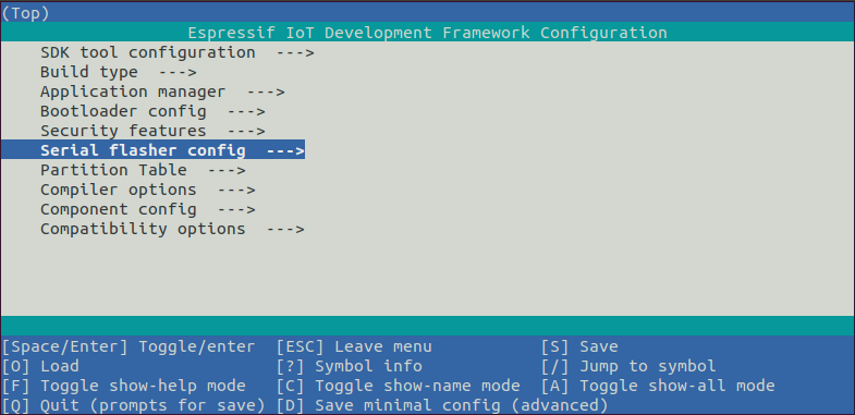
Project configuration — Home window 
You are using this menu to set up project specific variables, e.g. Wi-Fi network name and password, the processor speed, etc. Setting up the project with menuconfig may be skipped for “hello_word”. This example will run with default configuration.
If you use ESP32-DevKitC board with the ESP32-SOLO-1 module, or ESP32-DevKitM-1 board with the ESP32-MIN1-1(1U) module, enable single core mode ( CONFIG_FREERTOS_UNICORE ) in menuconfig before flashing examples.
The colors of the menu could be different in your terminal. You can change the appearance with the option —style . Please run idf.py menuconfig —help for further information.
Step 8. Build the Project
Build the project by running:
This command will compile the application and all ESP-IDF components, then it will generate the bootloader, partition table, and application binaries.
If there are no errors, the build will finish by generating the firmware binary .bin files.
Step 9. Flash onto the Device
Flash the binaries that you just built (bootloader.bin, partition-table.bin and hello_world.bin) onto your ESP32 board by running:
Replace PORT with your ESP32 board’s serial port name from Step 6. Connect Your Device .
You can also change the flasher baud rate by replacing BAUD with the baud rate you need. The default baud rate is 460800 .
For more information on idf.py arguments, see idf.py .
The option flash automatically builds and flashes the project, so running idf.py build is not necessary.
Encountered Issues While Flashing?
If you run the given command and see errors such as “Failed to connect”, there might be several reasons for this. One of the reasons might be issues encountered by esptool.py , the utility that is called by the build system to reset the chip, interact with the ROM bootloader, and flash firmware. One simple solution to try is manual reset described below, and if it does not help you can find more details about possible issues in Troubleshooting.
esptool.py resets ESP32 automatically by asserting DTR and RTS control lines of the USB to serial converter chip, i.e., FTDI or CP210x (for more information, see Establish Serial Connection with ESP32 ). The DTR and RTS control lines are in turn connected to GPIO0 and CHIP_PU (EN) pins of ESP32, thus changes in the voltage levels of DTR and RTS will boot ESP32 into Firmware Download mode. As an example, check the schematic for the ESP32 DevKitC development board.
In general, you should have no problems with the official esp-idf development boards. However, esptool.py is not able to reset your hardware automatically in the following cases:
Your hardware does not have the DTR and RTS lines connected to GPIO0 and CHIP_PU
The DTR and RTS lines are configured differently
There are no such serial control lines at all
Depending on the kind of hardware you have, it may also be possible to manually put your ESP32 board into Firmware Download mode (reset).
For development boards produced by Espressif, this information can be found in the respective getting started guides or user guides. For example, to manually reset an esp-idf development board, hold down the Boot button ( GPIO0 ) and press the EN button ( CHIP_PU ).
For other types of hardware, try pulling GPIO0 down.
Normal Operation
When flashing, you will see the output log similar to the following:
If there are no issues by the end of the flash process, the board will reboot and start up the “hello_world” application.
If you’d like to use the Eclipse or VS Code IDE instead of running idf.py , check out the Eclipse guide , VS Code guide .
Step 10. Monitor
To check if “hello_world” is indeed running, type idf.py -p PORT monitor (Do not forget to replace PORT with your serial port name).
This command launches the IDF Monitor application:
After startup and diagnostic logs scroll up, you should see “Hello world!” printed out by the application.
To exit IDF monitor use the shortcut Ctrl+] .
If IDF monitor fails shortly after the upload, or, if instead of the messages above, you see random garbage similar to what is given below, your board is likely using a 26 MHz crystal. Most development board designs use 40 MHz, so ESP-IDF uses this frequency as a default value.

If you have such a problem, do the following:
Exit the monitor.
Go to Component config –> ESP32-specific –> Main XTAL frequency, then change CONFIG_ESP32_XTAL_FREQ_SEL to 26 MHz.
After that, build and flash the application again.
You can combine building, flashing and monitoring into one step by running:
IDF Monitor for handy shortcuts and more details on using IDF monitor.
idf.py for a full reference of idf.py commands and options.
That’s all that you need to get started with ESP32!
Now you are ready to try some other examples, or go straight to developing your own applications.
Some of examples do not support ESP32 because required hardware is not included in ESP32 so it cannot be supported.
If building an example, please check the README file for the Supported Targets table. If this is present including ESP32 target, or the table does not exist at all, the example will work on ESP32.
Updating ESP-IDF
You should update ESP-IDF from time to time, as newer versions fix bugs and provide new features. The simplest way to do the update is to delete the existing esp-idf folder and clone it again, as if performing the initial installation described in Step 2. Get ESP-IDF .
After updating ESP-IDF, execute the Install script again, in case the new ESP-IDF version requires different versions of tools. See instructions at Step 3. Set up the tools .
Once the new tools are installed, update the environment using the Export script. See instructions at Step 4. Set up the environment variables .