Serial/UART Communication Between Two Arduino Boards
In this tutorial, we will perform UART or serial communication between two Arduino boards using UART software library of Arduino IDE. To debug and program Arduino using a USB port, the serial port which is known as Universal Asynchronous Receiver/Transmitter (UART) Communication is used. For most sensors and systems, the main communication method is considered to be UART. In order to share workload, information and perform different tasks; sometimes communication between to Arduino is necessary.
Communication between two Arduino boards using Software Serial
We will use a serial software library which is available in Arduino IDE. But the questions why we want to use the software UART library of Arduino when Arduino Uno has one UART port available on D0 and D1 pins. Because, Arduino only have one UART port and sometimes in embedded projects, we require more than one UART communication port to interface different sensors and modules such as GSM, GPS, Bluetooth, Xbee, etc.
The other important reason to use the uart software library is that the UART port of Arduino is used by the onboard USB connection. This USB connection transfers data to the Arduino IDE serial monitor using Rx and Tx pins.

Although Arduino Mega has up to four serial communication ports. But, maximum Ardiuno compatible boards do not have multiple serial ports. In this case, a specially implemented software library is used to simulate UART communication behavior on other digital input output pins of Arduino. It is very easy to simulate serial UART communication but it should be remembered that it does not have any dedicated hardware and it will utilize the resources of already given Arduino Board like memory and execution time. However, all the functions which are usually available in hardware serial ports can be simulated and utilized using software serial ports.
Arduino SoftwareSerial Library
Arduino IDE has a built-in software serial library which allows use to perform serial communication using other digital input-output pins. By using SoftwareSerial library, we can communicate with multiple devices or sensors over the UART interface.
To use this library, first include the header file of software serial library using this line:
After that create an instant or object of the software serial library with a name of your own choice. For example, this line creates an object with the name of UART0. As an argument, we pass the name of digital pins which we want to use for serial communication. First argument is a receiver pin(RX) and the second argument is a transmit pin (TX). Hence, this line sets pin2 as a Rx pin and pin3 as a Tx pin for UART0.
Connection Diagram Between Two Arduino Boards via Serial Pins
Following figure shows a connection diagram between two Arduino boards using digital pins to simulate a UART communication port using a pre-built library.
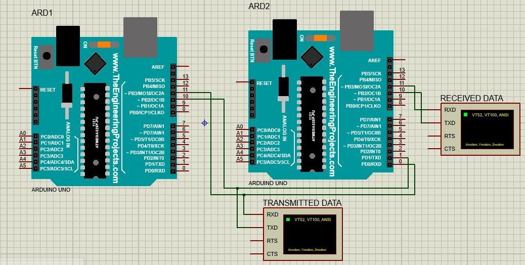
Consider we are using digital pin 11 and pin 10 as Tx and Rx for both Arduino boards.
- Connect virtual pin Tx of first Arduino board with pin Rx of second Arduino board.
- Connect virtual pin Rx of first Arduino board with pin Tx of second Arduino board.
- Virtual Tx pin of Arduino 1 transmit data to real buffer of receiver Arduino 2 and this data is written on virtual Tx pin of receiver Arduino 2 which is than shown on virtual terminal named as “Received Data”
- In order to monitor the status of transmitter and receiver Arduino, virtual terminals have been used.
- Connect the GND pin of both Arduino board together (if using real Arduino Boards)
- In case both Arduinos are not powered up using USB port than it is necessary to connect 5V pins of both Arduinos and power up one Arduino with USB port. (if using real Arduino Boards)
Serial Communication Code
The computer sends commands to Master Arduino, it is written on soft serial pins as defined in master code then it travels to the second Arduino through hardware connections made in pic 1 and it is communicated with Slave Arduino.
Code for Master Arduino
Description of Code for Master Arduino
Now lets see how above code works.
First includes the software serial library using its #include files. This line includes the SoftwareSerial.h library.
A serial object named as “softSerial” is declared here. Pin 10 will be used as Rx pin and pin 11 will be Tx pin. Using this “softSerial” object all functions of a normal serial connection can be used such as read, write and so on.
Here the baud rate of 9600 is being set for the softSerial object defined above. One important point to note here is that the baud rate of both Arduino boards such as master and slave should be same.
Here the statement “UART Communication” is being written repeatedly with a time delay of 0.1 second on Tx pin 11 of Arduino 1 for transmitting it to other Arduino.
Now add a delay of 100ms and this Arduino master will keep sending a string “UART Communication” on the transmit pin after every 100ms.
Code for Slave Arduino
Description of Code for Slave Arduino
This line includes the SoftwareSerial.h library.
SoftwareSerial softSerial () creates a serial object named as “softSerial” is declared here. Pin 10 will be used as Rx pin and pin 11 will be Tx pin. Using this “softSerial” object all functions of a normal serial connection can be used such as read, write and so on.
After that, this line sets the baud to 9600 for soft serial and serial communication.
Then presence of data is checked in buffer. if some data is available, it is stored in “ip” variable and then written on softserial transmit pin which is pin 11 of Arduino.
Proteus Simulation
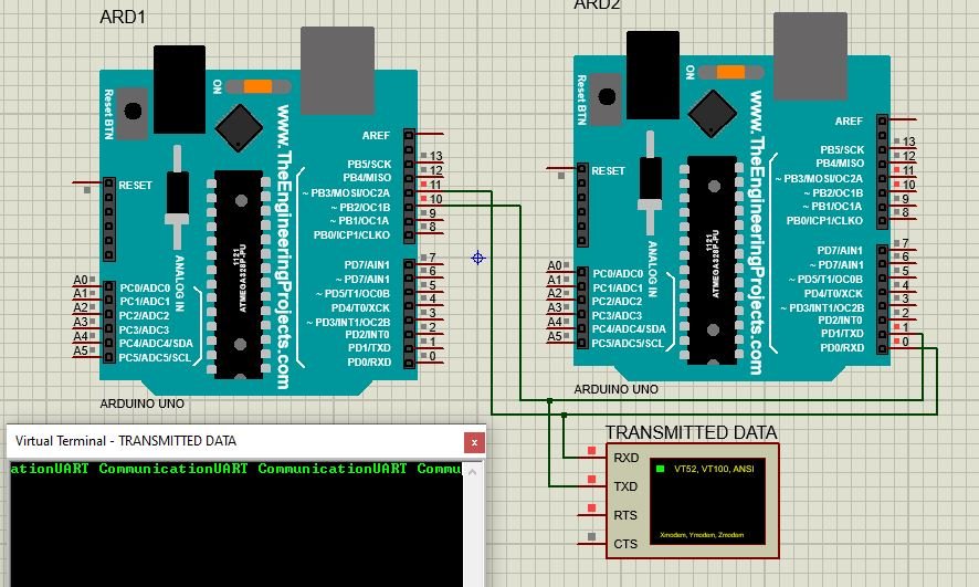
Figure above shows the circuit diagram for simulating this communication.
Below figure shows the data being sent by Master device through Tx pin 11 of Arduino 1.
Below figure shows the data sent by Master device and data received by Slave device at pin 11 of Arduino 2.

So data is successfully being transmitted using serial communication and soft serial library of Arduino.
Three most important points should be kept in mind while performing simulated serial communication.
- Tx pin of one Arduino board should be connected to Rx of other Arduino board. If opposite connections are made, Arduino board might get damage.
- Both Arduino boards must share same ground connection from sup
- Also, both Arduino boards should operate at same speed which means baud rate of both board should be same.
Control an LED via Serial Communication
Let us see another example of serial communication where the master will send either ‘1’ or ‘0’ to the slave. The slave will then receive that data and control an LED connected with its digital pin. We will use Software Serial to communicate between the two boards.
You will require the following components for this project.
Required Components
- Two Arduino UNOs
- One 5mm LED
- One 220 ohm resistor
- Connecting Wires
- Breadboard
Connection Diagram
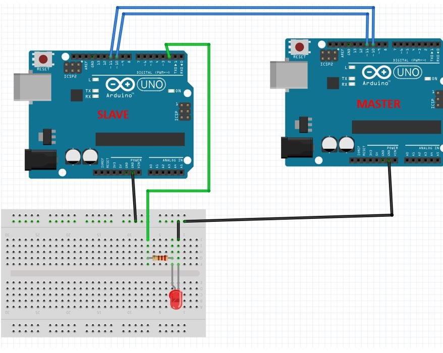
Connect virtual pin Tx of first Arduino board with pin Rx of second Arduino board. Connect virtual pin Rx of first Arduino board with pin Tx of second Arduino board. We will use Software Serial to configure pin 10 as RX and pin 11 as TX.
Anode pin of LED is connected with digital pin 2 (slave) through a 220 ohm current limiting resistor. The cathode pin is grounded.
Also make sure both Arduino boards have their grounds in common.
Code for Master Arduino
Description of Code for Master Arduino
Now lets see how above code works.
First includes the software serial library using its #include files. This line includes the SoftwareSerial.h library.
A serial object named as “softSerial” is declared here. Pin 10 will be used as Rx pin and pin 11 will be Tx pin. Using this “softSerial” object all functions of a normal serial connection can be used such as read, write and so on.
Here the baud rate of 9600 is being set for the softSerial object defined above. One important point to note here is that the baud rate of both Arduino boards such as master and slave should be same.
Here the master will send the number 1 and 0 to the slave after every 5 seconds.
Code for Slave Arduino
Description of Code for Slave Arduino
This line includes the SoftwareSerial.h library.
SoftwareSerial softSerial () creates a serial object named as “softSerial” is declared here. Pin 10 will be used as Rx pin and pin 11 will be Tx pin. Using this “softSerial” object all functions of a normal serial connection can be used such as read, write and so on.
A char variable called ‘number’ stores the data that the slave will receive from the master.
The LED is connected with the slave Arduino’s digital pin 2.
After that, this line sets the baud to 9600 for soft serial and serial communication.
Set the LED pin as an output pin using the pinMode() function. Specify the pin as the first parameter and the mode as the second parameter.
Inside the loop() function, we check if data is present in the buffer. If some data is available, it is stored in variable ‘number.’ Now if the number is ‘0’ then turn the LED OFF. If the number is ‘0’ then turn the LED ON.
The master will send ‘1’ and ‘0’ with a delay of 5 seconds continuously to the slave. Hence, the LED will stay ON for 5 seconds and then OFF for 5 seconds.
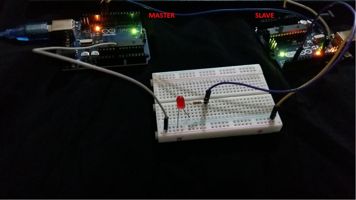
Hardware Demonstration
To see the demonstration, upload the master and sender codes to the two Arduino boards. But, before uploading code, make sure to select the Arduino board from Tools > Board and also select the correct COM port to which the Arduino board is connected from Tools > Port.

The LED will turn ON and stay ON for 5 seconds before turning OFF for 5 seconds. This continues as the master keeps on sending 1/0 to the slave.

Watch the video below:
Limitations of Software Serial Library
While using software serial communication following limitations should be kept in mind for successfully transmitting and receiving required data.
- Useable Pins
Every pin on the Arduino Board cannot be used as a Tx and Rx pin. For Tx generally, any of the available digital pins can be used but for Rx only pins which are interrupt enabled can be used.
- For Arduino Micro and Leonardo pin 8, 9, 10, 11, 14, 15, 16 can be used as Tx and Rx.
- On the other hand, for Arduino Mega pin 10, 11, 12, 13, 50, 51, 52, 53, 62, 63, 64, 65, 66, 67, 68, 69 can be used as TX and Rx.
- Interference
Simulated software serial communication uses resources of the same hardware. It uses the same timer as used by some other libraries. So some other functions can get effected if simulated serial port is used. The best known interference is with Servo Library.
- Multiple Software Connection:
Using this library, we can have multiple software simulated serial ports. But in this case only one port can receive data at one time. This can cause data loss. However, another software serial library is available which resolves this issue.
Connecting Two Nano Every Boards Through UART
In this tutorial we will control the built-in LED on the Arduino Nano Every from another Arduino Nano Every. To do so, we will connect both boards using a wired communication protocol called UART.
Note: This example would work connecting an Arduino Nano board with any other Arduino board, but be mindful that both board must work at the same voltage. If the operating voltage differ between connected boards, the board with the lower operating voltage could be damaged.
In this example, we will power both the Arduino boards through the computer, then we will use the Serial Monitor to send some commands to the Nano Every board, that will be connected through the UART with another Nano Every board. Depending on the commands received by the Nano Every board, it will turn ON or OFF its built-in LED.
Goals
The goals of this project are:
- Understand what the UART is.
- Use UART communication between two Arduino boards.
Hardware & Software Needed
For this project we will need:
- Arduino Nano Every
- Arduino Nano Every (or any other Arduino board that works at 5V)
- 2 x mini breadboard
- 3 x jumper wires
UART Communication
UART (Universal Asynchronous Receiver-Transmitter) is one of the most used device-to-device communication protocols. It allows an asynchronous serial communication in which the data format and transmission speed are configurable. The UART communication sends data bits one by one, from the least significant to the most significant, framed by start and stop bits so that precise timing is handled by the communication channel.
Embedded systems, microcontrollers, and computers mostly use UART as a form of device-to-device hardware protocol. Among the available communication protocols, UART uses only two wires for its transmitting and receiving ends, TX (Transmitter) and RX (Receiver). These pins are dedicated for that specific purpose, either transmitting or receiving.
Asynchronous means there is no clock signal to synchronize the output bits from the transmitting device going to the receiving end, but the baud rate needs to be the same on both the transmitting and receiving devices. The baud rate, is the rate at which information is transferred to a communication channel. In the serial port context, the set baud rate will serve as the maximum number of bits per second to be transferred.
UART is the communication protocol we use to communicate the PC to the board through the USB cable. In some older boards, TX and RX pins are used for communication with the computer, which means connecting anything to these pins can interfere with that communication, including causing failed uploads to the board. This is not the case for the Nano or MKR families, since these ones have two separate channels, using Serial for the communication with the computer and Serial1 for the communication with any other device through UART.
If you want to learn more about the UART protocol and how it works, you can check this link.
Circuit
In order to communicate both Arduino boards, we will need to connect them as shown in the image below.
The circuit.
At the moment of making the connections, we need to remember that this protocol has two dedicated lines TX and RX so we need to make sure to connect the TX pin, of one of the boards, with the RX of the other one. The same goes for the second, where his TX pin need to be connected to the RX pin of the first board.
To finish, it is very important that we connect the GND pins of both boards to each other. If we don't do this, the voltage reference will be different for each one of the boards so the communication won't work as intended.
Note: In order to enable serial communication, both Arduino boards must be connected to your computer via USB.
Creating the Program
1. Configuring the Receiver board
First, let's connect the Arduino Nano Every board to the computer and opening the Arduino Web Editor. This board will act as the receiver, which means that it will only receive data from the other board and turn ON or OFF the built-in LED according the received values. To start with the programming, start a new sketch and name it Nano_UART_receiver.
1.1. Receiver code walkthrough
Let's start inside the function. We need to initialize the built-in LED as and then turn it off. Then, we need to initialize the UART communication with the other board using the function.
Note: If you want to initialize the UART communication with any other Arduino board, please check here the serial port and the pins you need to use.
Inside the , we need to check if there is any byte available on the buffer using the function inside a statement. This configuration will run the portion of code inside the brackets of the only if there is any byte available to be read on the buffer of the UART1. If it is the case, we will read and store the available data in the variable using the function, since we want to read the data coming from the other Arduino board.
Now, we need to add a statement to check if the received data is or in order to turn on or off the built in LED respectively.
Note: When we use UART communication, all the data transmitted is text formatted, which means that we need to use character logic instead of numeric logic for compatibility. For example, in order to know if the data received is a "5" we need to check with the ASCII character of 5 ('5') instead of the numeric value of 5 (5). Therefore, we use dataReceived == '5' instead of dataReceived == 5.
1.2. Uploading the code to the receiver
Once we have finished the code, let's upload it to our Arduino Nano Every board. This board is now programmed to act as the receiver in this scenario. Once the code is uploaded, let's connect the other board to the computer.
Note: After uploading the code to the receiver board, it is not necessary for it to stay connected to the computer in order to function. However, it needs to be powered in order to work.
2. Configuring the Transmitter board
It is time to open a new sketch and name it as Nano_UART_transmitter, then let's start initializing the built in LED and the Serial communication as we did in the previous code but in this case since we need to read data also from the Serial Monitor we need to initialize the serial communication with the computer adding a function.
In the , we will use an statement to check if the data read from the Serial Monitor is equal to . If it is, we will use the function to send the same data to the other board. At the same time, we will turn on the built in LED of this board and print out a message in the Serial Monitor showing the state of the LED using the and functions respectively.
Then, using an statement, we need to do the same but in this case, if the data read from the Serial Monitor is equal to , we will turn the LED off.
2.1 Uploading the code to the transmitter
Once we have finished the code, let's upload it to our other Arduino Nano Every board. This board is now programmed to act as the transmitter.
3. Complete code
If you choose to skip the code building section, the complete code for both the receiver and the transmitter can be found below:
Receiver:
Transmitter:
Testing It Out
After you have successfully verified and uploaded the sketch to the two boards, make sure the transmitter board is connected and open the Serial Monitor. You need to enter a 1 to turn ON both LEDs, or a 0 to turn them OFF.

Serial Monitor output.
Troubleshoot
Sometimes errors occur, if the code is not working there are some common issues we can troubleshoot:
- Missing a bracket or a semicolon.
- Arduino board connected to the wrong port.
- Connection between the Arduino boards are not correct.
- Accidental interruption of cable connection.
Conclusion
In this simple tutorial we learned how to connect two Arduino boards so that they can communicate using UART communication.
Связь нескольких Arduino по проводу [GyverBus]
Не нашёл нормальных способов связать несколько Ардуинок в проводную сеть, решил сделать свой. Да, существуют библиотеки на базе Wire (например EasyTransfer), но там всё очень криво, по двум проводам и на слишком высокой частоте, т.е. на большом расстояние отправить не получится. В рассмотренной библиотеке предлагается использовать программный аналог интерфейса UART с двухсторонней связью по одному проводу, встроенным протоколом передачи, адресацией, упаковщиком и распаковщиком данных, контролем целостности и прочими приколами. Скорость интерфейса невысокая, что позволяет отправлять данные по проводам на очень большие расстояния и с высокой надёжностью, а лёгкая реализация вмещается даже в ATtiny13 на приём и на отправку. Расскажу немного о том, как работает интерфейс.
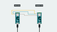
 Подключение производится по одному пину, земля (GND) должна быть общая. В сети могут находиться любые Ардуино – совместимые платы и МК, подключение – к любому GPIO (цифровому пину):
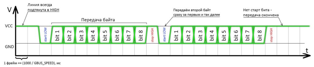
Сам интерфейс имеет такую же суть, как UART:
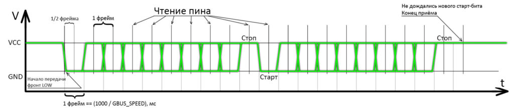
Чтение производится в ожидаемых серединах фреймов, начало отсчёта – стартовый LOW:
В начальный момент времени все устройства держат пин в подтянутом к питанию состоянии ( INPUT_PULLUP ). Передавать данные может только одно устройство. Все устройства в сети принимают данные одновременно, но в пакет входит адрес приёмника, поэтому приёмник поймёт, что данные предназначены ему. Остальные устройства проигнорируют принятый пакет.
Применение
Зачем нужен данный интерфейс? Можно собрать устройство с центральной базой (например на Arduino Nano) и несколькими удалёнными, например на копеечных ATtiny13. База будет общаться с удалёнными устройствами и отправлять им команды на исполнение (включить/выключить нагрузку, увеличить/уменьшить тепловую мощность, яркость и т.д.), а также может запрашивать данные с их датчиков. Связь по медленному цифровому протоколу получится очень надёжной даже на большом расстоянии (сотни метров), что избавляет от применения дополнительных конвертеров интерфейсов. Та же тинька 13 может отправлять на базу данные с датчиков температуры/влажности/освещённости и так далее.
Как ещё один вариант: индивидуальное управление яркостью освещения для цепи светильников в саду или на складе: в каждом светильнике стоит тинька и управляет яркостью своей лампы по команде с базы. Преимущество в том, что все светильники связаны между собой и вместе с базой всего двумя проводами.
А нужен ли GBUS?
Для передачи между двумя платами через Serial (обычный и software) можно использовать полностью стандартный способ: методы write() и readBytes(). Функции принимают байтовые массивы, но на ничего не мешает их обмануть и передавать что угодно, даже структуры:
О других способах читайте в уроке общение по Serial.
GBUS по сути делает то же самое, но предлагает дополнительные возможности:
- GBUS использует свои способы отправки и чтения байтов (на базе read, write и available), которые не блокируют выполнение остального кода на время чтения и отправки, в отличие от стандартных. На медленных скоростях это может быть критично.
- В GBUS встроена проверка целостности данных, в десятки раз увеличивающая надёжность передачи.
- GBUS превращает интерфейс в шину, то есть общаться могут не два устройства, а сколько угодно, так как имеют адресацию.
- GBUS даёт расширенную отладку ошибок по приёму данных.
- В GBUS есть встроенные функции, позволяющие “достучаться” до приёмника, то есть отправить ему запрос и дождаться корректного ответа.
БИБЛИОТЕКА
GyverBus v2.4
- Очень простой, надёжный, устойчивый к помехам и задержкам, но медленный интерфейс связи на базе UART
- Двухсторонняя связь по одному проводу
- Асинхронная отправка и чтение (на базе millis())
- Двухсторонняя совместимость с аппаратным UART
- Возможность принимать и отправлять данные внутри сети Ардуинок
- Адресация до 254 устройств в сети (от 1 до 255)
- Всеядная функция отправки и приёма (ест переменные, структуры, массивы)
- Встроенная проверка CRC (контроль целостности) пакета данных
- Возможность отправки и чтения короткого “запроса”
- Сама библиотека предоставляет возможности по отладке (коды ошибок)
- В примерах есть компактные варианты чтения и отправки данных, влезет даже в ATtiny
Поддерживаемые платформы: все Arduino (используются стандартные Wiring-функции)
УСТАНОВКА
- Библиотеку можно найти и установить через менеджер библиотек по названию GyverBus в:
- Arduino IDE (Инструменты/Управлять библиотеками)
- Arduino IDE v2 (вкладка “Library Manager”)
- PlatformIO (PIO Home, вкладка “Libraries”)
ДОКУМЕНТАЦИЯ
Особенности новой версии
В новой версии библиотеки протокол GBUS был полностью отделён от интерфейса: сейчас GBUS — это протокол связи, то есть порядок байтов в посылке (адрес, CRC и прочее). Общаться по GBUS можно при помощи любой Serial библиотеки, а точнее — любого объекта класса Stream (родная библиотека аппаратного Serial, включая Serial1, Serial2 и прочие на Arduino Mega, SoftwareSerial на любой Ардуино-совместимой платформе, а также встроенный в GyverBus однопроводной softUART). Это позволяет удобно, надёжно и не блокируя выполнение остального кода передавать наборы данных любых типов между Ардуино-совместимыми платами (Arduino, esp8266, esp32) при помощи программного или аппаратного UART’a.
Отправка широковещательных сообщений (new!)
В версии 2.3 добавлена возможность отправки сообщений «всем» по адресу 255: любой приёмник получает сообщение, отправленное на его личный адрес и на адрес 255.
Особенности библиотеки
Библиотека содержит в себе несколько наборов инструментов:
- GyverBus.h — базовый набор инструментов для работы с протоколом GBUS: функции для упаковки, распаковки и проверки байтовых массивов для передачи и приёма данных. Функции можно использовать отдельно от всего остального для упаковки-распаковки и проверки данных для передачи по любому интерфейсу связи, просто передавая любые данные как байтовый массив.
- GBUS.h — класс GBUS, который позволяет удобно общаться по протоколу GBUS через любой «Serial». В отличие от родных инструментов класса Stream не блокирует выполнение кода на приём и отправку, что очень критично на невысоких скоростях.
- softUART.h — однопроводной UART, работающий на приём и отправку, не блокирующий выполнение кода. Может использоваться для библиотеки GBUS, так как наследует класс Stream.
- GBUSmini.h — набор отдельных функций для общения по GBUS. Все функции блокируют выполнение кода на время приёма/отправки (сделаны на базе delay() ), но реализованы максимально легко и позволяют работать с шиной даже на ATtiny13. Для работы нужно подключить библиотеку и просто использовать нужные функции из доступных.
Подключение для softUART
Платы/микроконтроллеры объединяются в шину одним дата-проводом и должны иметь общую землю GND. Пин шины — любой обычный GPIO (цифровой пин входа-выхода). Пин должен быть подтянут к питанию внутренним (режим INPUT_PULLUP ) или внешним резистором (5-100 кОм). При использовании GyverBus.h внутренняя подтяжка включается автоматически, а для GBUSmini.h её нужно прописать самому (см. примеры). Схема подключения — на самой первой картинке этой страницы сайта.
Для удалённого подключения рекомендуется использовать экранированный провод, экран нужно подключить на GND. Если подключение производится двумя обычными проводами (GND и дата) — провода рекомендуется скрутить в косичку для защиты от наводок.
Подключение для Serial
Для одностороннего общения по классическому Serial достаточно соединить TX передатчика и RX приёмника. Для двухсторонней связи нужно будет соединить ещё и RX передатчика и TX приёмника. Например для использования функций «достукивания» до приёмника, чтобы удостовериться в том, что он получил данные.
Общение по шине
Шина двухсторонняя, любое из устройств в сети может быть отправителем и получателем, но в один момент времени может осуществляться только одна передача: один передаёт — все слушают. Такая логика работы позволяет всем устройствам общаться по очереди между собой без ограничений.
Совместимость softUART
softUART имеет такие же контрольные биты и тайминги, как у UART (в ардуиновской среде — Serial), и полностью с ним совместим, то есть можно отправлять данные по Serial (с ноги TX) и принимать на softUART, либо отправлять c softUART и принимать по Serial (на ногу RX). Скорость Serial нужно выставлять выше 250 бод, softUART соответственно тоже.
Скорость
- softUART — скорость задаётся при создании объекта.
- GBUS — скорость задаётся у самого интерфейса, например у «Serial’ов» это begin.
- GBUSmini — скорость задаётся в GBUSmini.h, параметром GBUS_DEFAULT_SPEED, либо дефайном GBUS_SPEED в скетче перед подключением библиотеки.
Скорость задаётся в бодах (baud rate) и совпадает с бодрейтом UART’а. Время передачи одного байта равно 10 / baud секунд, соответственно скорость передачи составляет baud / 10 байт в секунду (например при скорости 300 бод — 30 байт в секунду).
Примечание: чем ниже скорость, там надёжнее передача и тем меньше влияют помехи, индуктивность линии и несовпадение частот тактирования у передатчика и приёмника. Скорость должна быть одинаковой для всей шины, т.е. всех подключенных к ней устройств!
Максимальная скорость
Максимальная скорость ограничена прежде всего соединением: длиной проводов, наличием экрана, наличием источников помех и прочим. В идеальных условиях скорость будет такая:
При использовании в качестве интерфейса аппаратного Serial скорости могут быть очень большие, вплоть до 1000000 бод.
При использовании в качестве интерфейса программного Serial читайте описание к нему. Ардуиновский софтсериал обещает стабильную передачу на скоростях вплоть до 115200. В то же время он блокирует код и запрещает прерывания, что может быть очень плохо.
При использовании в качестве интерфейса softUART очень важен частый вызов tick(): рекомендуется делать это не реже, чем каждые 1 000 000 / baud / 4 микросекунд. При наличии в остальном коде задержек или блокирующих выполнение участков на время, превышающее четверть времени бита, передача на высоких скоростях может происходить с ошибками. Можно вызывать tick() по прерыванию таймера. Ещё можно сделать так:
При использовании библиотеки GBUSmini.h максимальная скорость ограничена частотой опроса читающих функций (вызывать не реже, чем каждые 1 000 000 / baud / 4 микросекунд) и точностью настройки коррекции: в GBUSmini.h в секции настроек есть параметры GBUS_DEFAULT_WRITE и GBUS_DEFAULT_READ . Они отвечают за коррекцию задержки в микросекундах на отправку и чтение одного бита. Это значение зависит от частоты тактирования МК ( пропорционально! ), модели самого МК, версии «ядра» Arduino и подбирается вручную. Также значение коррекции может меняться в зависимости от скорости шины! Привожу некоторые известные:
МК Ядро GBUS_DEFAULT_WRITE GBUS_DEFAULT_READ ATmega328p (Arduino Nano) Стандартное версии 1.8.3 8 (при 16 MHz) 5 (при 16 MHz) Максимальная скорость с учётом «пустого» скетча и откалиброванными значениями коррекции задержки, платы соединены на бредборде проводами длиной 10см:
Отправитель — приёмник Макс. скорость softUART — softUART 25’000 GBUSmini — GBUSmini 10’000 softUART — GBUSmini 15’000 GBUSmini — GBUSmini 10’000 Улучшение связи
Предложено Саней Чёрным. Есть предложение по улучшению помехоустойчивости работы на дальние дистанции. К примеру имеем 30 устройств на линии. У каждого подтяжка к + внешняя по 100К. В сумме считаем это как параллельное соединение резисторов и при передаче LOW(0-ка) нужно пересилить 3.45кОм это 1.45мА на вывод. Все вроде как хорошо, но если в этом же кабеле( к примеру ПВС4*1 — четырехжильный кабель с сечением 1мм^2) рядом идет 220VAC, то на линию GND Arduin-ы будет идти нехилая наводка, которая на длине в 100м(а это всего 50м от передатчика, т.к. 50м провод данных и 50м провод земли) приведет к целому ряду ложных приемов пакетов. Поэтому предлагаю схему, которая позволит каждому устройству на линии при получении LOW дублировать его. Это влечет за собой уменьшение скорости передачи данных. Т.к. каждая оптопара имеет задержку в 4мкс. А на 30 последовательно соединенных устройствах это 0.12мс.

Контроль целостности
В библиотеку встроен контроль целостности данных (включен по умолчанию): последним байтом в пакете передаётся crc (очевидно 8-ми битный). Приёмник считает CRCвсего пакета, и если он совпадает — приём считается успешным. CRC повышает надёжность передачи данных: даже если один бит будет передан неправильно — приёмник отбракует посылку.
Примечание: у прошивок всех устройств в сети CRC должен быть или включен, или выключен. Устройство, настроенное на приём данных с CRC не сможет принять пакет без CRC.
Проверку CRC можно отключить и в основной библиотеке, и в мини-версии. Зачем отключать? Позволит сэкономить чутка памяти. Лучше не отключать CRC, надёжность передачи данных сильно снизится.
Протокол связи
Протоколом здесь назван порядок и значение байтов в пакете:
Тип посылки Байт 1 Байт 2 Байт 3 Байт 4 Байт 4+n Байт 4+n+1 Данные Количество байт Адрес получателя Адрес отправителя Байт даты 1 Байт даты n CRC Тип посылки Байт 1 Байт 2 Байт 3 Байт 4 Запрос (request) 0 Адрес получателя Адрес отправителя CRC Тип посылки Байт 1 Байт 2 Байт 3 Байт 4 Ответ (ack) 1 Адрес получателя Адрес отправителя CRC Таким образом например пакет [5, 3, 8, 123, 456, 12] содержит 6 байт, предназначен для устройства с адресом 3 и отправлен с адреса 8. Байты данных имеют значение 123 и 456, а CRC — 12.
Оба способа взаимодействия с GBUS работают по этому протоколу и совместимы между собой. Если стоит задача сформировать пакет вручную, отправить и принять его через функции из библиотеки — пакет должен быть сформирован согласно протоколу.
Адресация
В GBUS используется 8-ми битная адресация, но адрес 0 зарезервирован как код ошибки чтения в GBUSmini.h. Таким образом адресовать устройства можно с 1 по 255 адрес.
Если не работает
Самая нестабильная передача — между softUART и GBUSmini, а также между устройствами на базе разных микроконтроллеров и/или с разной частотой тактирования. Первым делом стоит попробовать чуть увеличить или чуть уменьшить значения коррекции задержки.
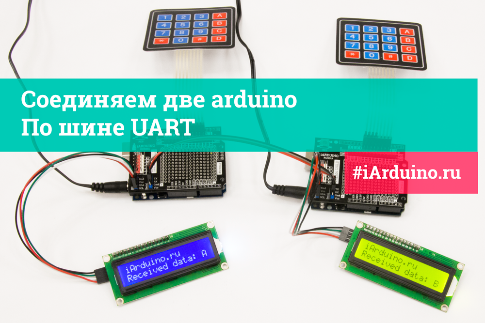
Урок 26.1 Соединяем две arduino по шине UART
При создании некоторых проектов, требуется разделить выполняемые задачи между несколькими Arduino.
В этом уроке мы научимся соединять две Arduino по аппаратной шине UART.
Преимущества:
- Простота реализации.
- Дуплексная связь, обе Arduino могут одновременно передавать данные друг другу.
Недостатки:
- Нет возможности «залить» скетч, при наличии устройств на аппаратной шине UART.
- Реализуется соединение только двух устройств (при отсутствии доп. модулей).
Нам понадобится:
-
х 2шт.
- LCD дисплей LCD1602 IIC/I2C(синий) или LCD1602 IIC/I2C(зелёный) х 2шт. х 2шт. х 2шт. х 2шт.
- Шлейф «мама-мама» (3 провода) для шины UART x 1шт.
Для реализации проекта нам необходимо установить библиотеки:
- Библиотека iarduino_KB (для подключения матричных клавиатур).
- Библиотека LiquidCrystal_I2C_V112 (для подключения дисплеев LCD1602 по шине I2C).
О том как устанавливать библиотеки, Вы можете ознакомиться на странице Wiki — Установка библиотек в Arduino IDE .
Видео:
Схема подключения:
Подключение LCD дисплея осуществляется к аппаратным выводам шины I2C.
Клавиатура подключается к любым цифровым выводам, в примере используются выводы 2-9.
Соединение двух arduino осуществляется по шине UART:Arduino 1 Arduino 2 TX (transmit — передать) RX (receive — получить) RX (receive — получить) TX (transmit — передать) GND (ground — земля) GND (ground — земля) 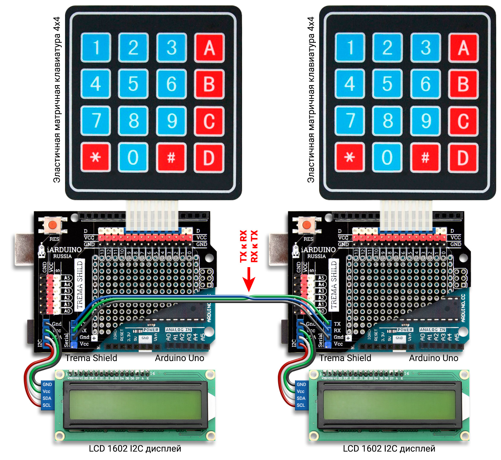
Код программы:
Настройка параметров шины UART:
Максимальная, аппаратно реализуемая частота передачи данных, может достигать 1/8 от тактовой частоты.
Настройка шины осуществляется вызовом функции begin() класса Serial, с передачей ей до двух аргументов. Первый аргумент устанавливает частоту передачи данных (в примере 9600 бод), второй (необязательный) аргумент устанавливает количество битов, наличие проверки на четность/нечетность, длину стопового бита (по умолчанию SERIAL_8N1).
Допустимые значения второго аргумента функции begin() класса Serial:
- SERIAL_5N1
- SERIAL_6N1
- SERIAL_7N1
- SERIAL_8N1
- SERIAL_5N2
- SERIAL_6N2
- SERIAL_7N2
- SERIAL_8N2
- SERIAL_5E1
- SERIAL_6E1
- SERIAL_7E1
- SERIAL_8E1
- SERIAL_5E2
- SERIAL_6E2
- SERIAL_7E2
- SERIAL_8E2
- SERIAL_5O1
- SERIAL_6O1
- SERIAL_7O1
- SERIAL_8O1
- SERIAL_5O2
- SERIAL_6O2
- SERIAL_7O2
- SERIAL_8O2
Значения отличаются последними тремя символами, которые означают следующее:
- Первая цифра: указывает количество бит в минимальной посылке (от 5 до 8).
- Буква N/E/O: E-проверка четности, O-проверка нечетности, N-без проверки.
- Последняя цифра: указывает длину стопового бита (1 или 2 битовых интервала)
Таким образом значение по умолчанию SERIAL_8N1 означает, что в минимальной посылке 8 бит (без учёта стартового и стопового битов), данные передаются без проверки на чётность/нечётность, длина стопового бита равна 1 битовому интервалу.
Настройки шины UART обеих arduino должны быть идентичны!