
Подключение реле
Реле Ардуно позволяет подключить устройства, работающие в режимах с относительно большими токами или напряжения. Мы не можем напрямую подключить к плате Arduino мощные насосы, двигатели, даже обычную лампочку накаливания — плата не предназначена для такой нагрузки и работать не будет. Именно поэтому нам придется добавить в схему реле, который вы можете встретить в любом проекте.
Рис. 1 — Реле для Arduino
Принцип действия реле
Реле — это шлюз, который позволяет соединить вместе электрические цепи с совершенно разными параметрами. Обычный шлюз на реке соединяет водные каналы, расположенные на разной высоте, открывая или закрывая ворота. Реле в Arduino включает или выключает внешние устройства, определенным образом замыкая или размыкая отдельную электрическую сеть, в которую они подключены. С помощью Arduino и реле мы управляем процессом включения или выключения так же, как включаем или выключаем свет дома — подавая команду на замыкание или размыкание. Arduino подает сигнал, само же замыкание или размыкание «мощной» цепи будет делать реле через специальные внутренние механизмы. Реле можно представить себе в виде дистанционного пульта, с помощью которого мы выполняем нужные действия с помощью относительно «слабых» сигналов.
 Рис. 2 — Обозначение реле на схемах
Реле характеризуется следующими параметрами:
- Напряжение или ток срабатывания.
- Напряжение или ток отпускания.
- Время срабатывания и отпускания.
- Рабочие ток и напряжение.
- Внутреннее сопротивление.
В зависимости от типа этих внутренних размыкающих механизмов и особенностях устройства можно выделить две основные группы реле: электромеханические реле (включение с помощью электромагнита) и твердотельные реле (включение через специальные полупроводниковые компоненты).
Электромагнитные и твердотельные реле
Электромагнитное реле
 Рис. 3 — Реле для Arduino
Электромагнитное реле – это электрическое устройство, которое механическим путем замыкает или размыкает цепь нагрузки при помощи магнита. состоит из электромагнита, подвижного якоря и переключателя. Электромагнит – это провод, который намотан на катушку из ферромагнетика. В роли якоря выступает пластина из магнитного материала. В некоторые модели устройства могут быть встроены дополнительные электронные компоненты: резистор для более точного срабатывания реле, конденсатор для уменьшения помех, диод для устранения перенапряжений.
Работает реле благодаря электромагнитной силе, возникающей в сердечники при подаче тока по виткам катушки. В исходном состоянии пружина удерживает якорь. Когда подается управляющий сигнал, магнит начинает притягивать якорь и замыкать либо размыкать цепь. При отключении напряжения якорь возвращается в начальное положение. Источниками управляющего напряжения могут быть датчики (давления, температуры и прочие), электрические микросхемы и прочие устройства, которые подают малый ток или малое напряжение.
Электромагнитное реле применяется в схемах автоматики, при управлении различными технологическими установками, электроприводами и другими устройствами. Реле предназначено для регулирования напряжений и токов, может использоваться как запоминающее или преобразующее устройство, также может фиксировать отклонения параметров от нормальных значений.
Классификация электромагнитных реле:
- Управляющий ток может быть как постоянным, так и переменным. В первом случае устройство может быть нейтральным или поляризованным. Для переменного тока якорь выполняется из электротехнической стали, чтобы уменьшить потери.
- Якорное или герконовое реле. Для якорного процесс замыкания и размыкания происходит при помощи перемещения якоря, для герконового характерно отсутствие сердечника, магнитное поле воздействует на электрод с контактами.
- Быстродействие – до 50 мс, до 150 мс и от 1 с.
- Зщитное покрытие – герметизированное, зачехленное и открытое.
По сравнению с полупроводниковыми устройствами электромагнитное реле обладает преимуществами – оно стоит недорого, коммутация большой нагрузки при небольшом размере устройства, малое выделение тепла на катушке. Из недостатков можно выделить медленное срабатывание, помехи и сложность коммутации индуктивных нагрузок.
Твердотельные реле
 Рис. 4 — Твердотельное реле для Arduino
Твердотельные реле считаются хорошей альтернативой электромагнитным, они представляет собой модульное полупроводниковое устройство, которое производится по гибридной технологии. В составе реле имеются транзисторы, симисторы или тиристоры. По сравнению с электромагнитными устройствами твердотельные реле обладают рядом преимуществ:
- Долгий срок эксплуатации.
- Быстродействие.
- Малые размеры.
- Отсутствуют посторонние шумы, акустические помехи, дребезги контактов.
- Низкое потребление энергии.
- Качественная изоляция.
- Стойкость к вибрации и ударам.
- Нет дугового разряда, что позволяет работать во взрывоопасных местах.
Работают по следующему принципу: подается управляющий сигнал на светодиод, происходит гальваническая развязка управляющей и коммутируемой цепей, затем сигнал переходит на фотодиодную матрицу. Напряжение регулирует силовым ключом.
Твердотельные реле также имеют несколько недостатков. Во-первых, при коммутации происходит нагрев устройства. Повышение температуры устройства приводит к ограничению регулируемого тока – при температурах, превышающих 60 градусов, уменьшается величина тока, максимальная рабочая температура 80 градусов.
Твердотельные реле классифицируются по следующим признакам:
- Тип нагрузки – однофазные и трехфазные.
- Способ управления – коммутация происходит за счет постоянного напряжения, переменного или ручного управления.
- Метод коммутации: контроль перехода через ноль (применяется для слабоиндуктивных, емкостных и резистивных нагрузок), случайное включение (индуктивные и резистивные нагрузки, которым необходимо мгновенное срабатывание) и фазовое управление (изменение выходного напряжения, регулировка мощности, управление лампами накаливания).
Реле в проектах Arduino
Наиболее распространенное реле для платы Arduino выполняется в виде модуля, например, SONGLE SRD-05VDC. Устройство управляется напряжением 5 В, может коммутировать до 10 А 30 В DC и 10 А 250 В AC.
Схема изображена на рисунке. Реле состоит из двух не связанных между собой цепей – управляющая цепь А1 и А2 и управляемая 1, 2 и 3.
 Рис. 5 — Схема реле для Arduino
Между А1 и А2 имеется металлический сердечник. Если по нему проходить электрический ток, к нему притянется якорь 2. 1, 3 – неподвижные контакты. При отсутствии тока якорь будет около контакта 3.
Подключение реле к Arduino
Рассмотрим одноканальный модуль реле. Он имеет всего 3 контакта, подключаются они к Arduino Uno следующим образом: GND – GND, VCC — +5V, In – 3. Вход реле – инвертирован, так что высокий уровень на In выключает катушку, а низкий – включает.
 Рис. 6 — Одноканальный модуль реле для Arduino
Светодиоды нужны для индикации – при загорании красного LED1 подается напряжение на реле, при загорании зеленого LED2 происходит замыкание. Когда включается микроконтроллер, транзистор закрыт. Для его открытия на базу нужен минус, подается при помощи функции digitalWrite(pin, LOW); . Транзистор открывается, протекает ток через цепь, реле срабатывает. Чтобы его выключить, на базу подается плюс при помощи digitalWrite(pin, HIGH); .
Схема подключения лампы и внешний вид макета представлены на рисунках.

 Рис. 7 — Схема подключения лампы и реле к Arduino
Простой вариант управления реле
В данном примере используется стандартный модуль реле Arduino, на котором уже установлены все необходимые элементы для подключения к Arduino. Схема подключения очень проста: модуль реле присоединяется к 5 пину платы Arduino. При этом для простоты мы можем даже не присоединять реальную нагрузку — реле будет щелкать при каждом изменении состояния, мы услышим эти щелчки и будем понимать, что скетч работает.
 Рис. 8 — Схема подключения лампы и реле к Arduino
Скетч
Скетч управления реле с датчиком движения
В реальных проектах изменение состояния реле должно происходить в ответ на какую то реакцию среды. Например, в ответ на сигнал сработавшего датчика движения можно включить свет, замкнув цепь с помощью реле. В данном скетче мы рассмотрим такой вариант подключения.
 Рис. 9 — Схема подключения реле с датчиком движения
Следует понимать, что в реальных проектах обходятся вообще без Arduino — просто подключая сигнальный выход датчика к реле.
Скетч
В данном примере мы добавим в цикл loop проверку состояния PIR-датчика с помощью функции digitalRead () . Если мы получаем HIGH , то это означает сработку датчика и мы выполняем действие — включаем реле. Если к нему присоединить лампочку, то она загорится. Но, как и в прошлом примере, можно просто послушать щелчки.
Arduino и реле
Электромагнитное реле – универсальный способ коммутировать нагрузку. Универсальность в том, что реле имеет чисто механический контакт, то есть физически замыкает контакты. Это позволяет коммутировать нагрузку как переменного, так и постоянного тока в широком диапазоне напряжений: от 0 до сетевого, то есть 220 Вольт. По току производитель обещает 10 А, то есть можно коммутировать например 2 кВт обогреватель. Само реле напрямую к микроконтроллеру подключать нельзя, поэтому для управления силовая схема развязывается с логической, соответственно китайцы выпускают несколько типов модулей реле:
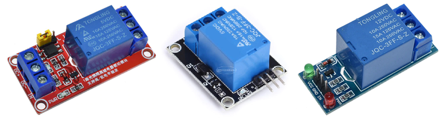
В наборе идёт красный модуль с настройкой логического уровня (жёлтый джампер-перемычка между буквами H и L). В центре – самый дешёвый модуль с минимальной обвязкой, высокого уровня. И справа – тоже неплохой модуль, но низкого уровня, что не всегда удобно использовать. Примечание: реле высокого уровня переключается при высоком сигнале на логический вход, а низкого – низком. Все модули реле имеют три пина на одном конце и три на другом:
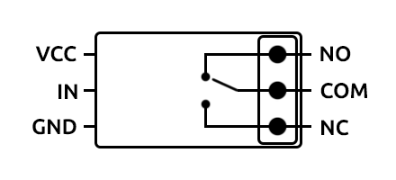
Слева находятся пины питания и управления самого реле:
- VCC (DC+, +) – питание
- GND (DC-, -) – “земля”
- IN (S) – логический управляющий сигнал
Справа находятся выходы самого реле, это одна контактная группа с переключением:
- COM (Common) – общий контакт
- NO (Normal Open) – нормально разомкнутый относительно COM контакт
- NC (Normal Close) – нормально замкнутый относительно COM контакт
Работает это следующим образом: само реле (синяя коробочка на плате) питается от VCC и GND и подключается на питание схемы, так как реле потребляет около 60 мА при переключении. Но управляется реле логическим сигналом от микроконтроллера, который подаётся на пин IN. На выходе реле наблюдается следующая картина: у неактивного реле замкнуты контакты COM и NC. При активации реле контакт переключается и COM замыкается с NO.
Реле высокого уровня будет включаться и потреблять ток при подаче высокого сигнала (5, 3.3V), а низкого – при подаче низкого (GND, 0V). Чисто логически удобнее использовать реле высокого уровня: подали высокий сигнал – реле включилось. Мы кстати разбирали реле вот в этом уроке. И вот в этом:
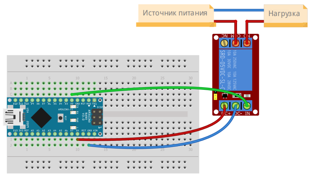
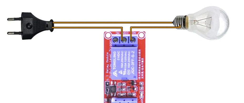
Подключение
Примеры
Для активации реле достаточно подать высокий сигнал (для реле из набора) на логический вход. Для примера и проверки подойдёт и классический пример “мигания светодиодом”:
ESP8266 first project: home automation with relays, switches, PWM, and an ADC

ESP8266 by Espressif Systems is a popular low-cost microcontroller chip with a full TCP/IP and Wi-Fi stack. A number of features are supported, making it easy to interface with various hardware to put it online, making this inexpensive chip a prominent player in the emerging home automation and Internet of Things (IoT) space.
It can be acquired cheaply from various sources, this is where I bought mine, from a vendor on Aliexpress:
-
, $2.63 (price since increased)
I ordered it some time ago, and it took a total of 54 days to arrive at my doorstep after placing my order. Other reviews also complain about the slow shipping, so you might be better off with a faster vendor, nonetheless it was a great deal for only a few dollars with free shipping. Long wait, but it finally arrived and I am ready to begin my first project with the fabled ESP8266:
Initial setup
Some of the steps required to initially get started with this board are non-obvious, detailed below.
USB to Serial
Plugged in a USB cable into the ESP8266 board, then to my computer. The onboard blue LED briefly flashed on then off, same behavior when I pressed the RST (reset) button, but no serial device appeared in /dev/tty.* or /dev/cu.*. Held down the “FLASH” button while powering up, no difference.
Peeled off the foam on the back the header pins were pushed in, found these helpful instructions:
- Install CH340G driver
- Use 9600bps baud rate
- Connect to WiFi
And the text “wemos.cc LoLin NodeMcu v3”
What is this CH340G driver? A USB/serial chip, similar to FTDI’s. Found this helpful guide: How To Use Cheap Chinese Arduinos That Come With With CH340G / CH341G Serial/USB Chip (Windows & Mac OS-X). Installed the CH34x_Install.zip driver linked there on macOS Sierra, rebooted and… kernel panic! Whenever I plugged in the device, the system froze hard.
First thought was to try to use an alternative USB-to-serial converter (such as the SparkFun FTDI Basic Breakout — 3.3V), wired directly to the ESP8266’s RX, TX, G, and 3V pins. No luck with this approach, but fortunately I found an updated driver:
adrianmihalko/ch340g-ch34g-ch34x-mac-os-x-driver
ch340g-ch34g-ch34x-mac-os-x-driver — CH340G CH34G CH34X Mac OS X driver
this driver worked great, with the USB serial device appearing under /dev/tty.wchusbserial*. Connecting with screen:
screen -L /dev/tty.wchusbserial1420 9600
I see some data when booting up. To interact with this device, use esptool:
themadinventor/esptool
esptool — ESP8266 ROM Bootloader utility
As a simple first step, let’s try reading the MAC address:
esptool.py —port /dev/tty.wchusbserial1420 —baud 9600 read_mac
esptool.py v1.1
Connecting…
We can connect to the device. Now to program it.
ESP8266 Arduino?
There are a plethora of development environments for the ESP8266. Not knowing what is best, I first installed esp8266/Arduino.
esp-hello-world looks like a good example program to try. Or how about ESP8266 NodeMCU — Getting started (Hello World), which uses ESPlorer:
What is this gibberish? Tried changing baud rate 9600 to 115200, better:
“Ai-Thinker Technology Co. Ltd. ready”, looks promising. Can I upload Lua?
Not sure what firmware this board came preinstalled with, but it would probably be a good idea to reflash it anew with something I know.
NodeMcu (Lua)
A guide to updating the firmware to NodeMCU: Update ESP8266 development kit NodeMCU firmware using OS X. You can get custom builds at https://nodemcu-build.com, with whatever modules you want. Cool, BME280 is an option, I’ll take it. Modules I added:
- BME280: temperature/pressure/humidity sensor, I used this chip in Home automation with Raspberry Pi + Homebridge with a Pi Zero, potentially overkill, perhaps switch to using it with the ESP8266?
- file: enabled by default, adds filesystem access, seems useful
- GPIO: blink lights… or control relays or contact sensors
- HTTP: web, a common transport layer for networking
- I²C: inter chip communication protocol
- mDNS: for Bonjour discovery
- net: networking, that’s kind of the point of the ESP8266
- node: enabled by default, various information
- PCM: pulse code modulation, play sound.. can I replace the Electronic Woodpecker from Electronic project kits: hands on with a vintage 160-in-1, or better?
- PWM: pulse width modulation, control brightness or speed
- sigma-delta: hardware signal generator, seems useful
- SPI: serial peripheral interface
- timer: sleeps and delays
- UART: serial communication
- WiFi: why I bought the ESP8266 in the first place. I like how it is a simple check box, no need for complicated driver setup as with Raspberry Pi Zero Wi-Fi USB Adapter Installation: TP-Link Archer T2U.
But Lua is so passé (and strange and unfamiliar), what about MicroPython?
ESP8266 MicroPython
Adafruit: MicroPython Basics: How to Load MicroPython on a Board is an excellent guide to installing MicroPython. Loaded it up and got to the REPL:
$ screen /dev/tty.wchusbserial1420 115200
MicroPython v1.8.5–10-g0e69e6b on 2016–10–17; ESP module with ESP8266
Type “help()” for more information.
>>>
Sweet, this is a more familiar environment. There is even a nifty web-based websocket client, MicroPython WebREPL. Good documentation, too.
Connect to WiFi using the network module, as a station (client):
then most of my programming was through the WebREPL.
First, back to the hardware.
Interfacing the Hardware
Comparison of ESP8266 NodeMcu development boards, I have the LoLin version, aka “V3”. Also ordered a WeMos D1 Mini V2 for $4, this seems to be one of the most popular ESP8266 boards, but I haven’t gotten it yet. TODO: test once I get it. Note this is not even considering the brand new ESP-32S chips with Bluetooth, but those cost much more than the ESP8266.
Back to the LoLin V3 board.
GPIO: LED
Available pins are: 0, 1, 2, 3, 4, 5, 12, 13, 14, 15, 16, which correspond to the actual GPIO pin numbers of ESP8266 chip. Note that many end-user boards use their own adhoc pin numbering (marked e.g. D0, D1, …). As MicroPython supports different boards and modules, physical pin numbering was chosen as the lowest common denominator. For mapping between board logical pins and physical chip pins, consult your board documentation.
What pin blinks the onboard blue LED? D3 = GPIO0 = FLASH (this is the pushbuton input, not an output) but Pin(0,Pin.OUT).high() had no effect. D0 = GPIO16 = USER = WAKE seems like a good guess, but Pin(16,Pin.OUT).high() didn’t light up the LED either. The LED happens to be active-low, so I retested with low(), no effect. Try them all:
>>> for p in [0, 1, 2, 3, 4, 5, 12, 13, 14, 15, 16]: pin=Pin(p,Pin.OUT);pin.high()
This blinked the blue LED, but also hung the REPL. Reset and try again. And then continue reading the documentation:
Note that Pin(1) and Pin(3) are REPL UART TX and RX respectively. Also note that Pin(16) is a special pin (used for wakeup from deepsleep mode)
Pin(1) = GPIO1 = TXD0
Pin(3) = GPIO3 = RXD0
so stay away from these pins, at least when in the REPL.
D0 = GPIO16 looks like a good pin to test with. Set it high, measure the voltage with a multimeter, set to low. Works as expected. Progress.
D3 = GPIO0 is wired to the “FLASH” pushbutton. Active-low, try reading then pressing the button to read the value:
Now to add an LED. According to GPIO Maximum current Imax, maximum source current on a GPIO is about 12 mA. We could use a transistor to drive the LED with greater current, or simply use an appropriate current-limiting resistor to only supply 12 mA to the LED:
R = V/I = (3.3 V)/(12 mA) = 275 Ω
or to keep it simple, a 330 Ω resistor for 10 mA. Wired a green LED with a water clear lens (as opposed to diffuse) and tested:
from machine import *
Pin(16,Pin.OUT).high()
Pin(16,Pin.OUT).low()
Could use this green LED as some sort of visual status indicator.
PWM: Buzzer
Next up: using PWM to drive a buzzer, both the buzzer from the microwave oven in Emerson MW8675W microwave oven teardown and the UPS from a salvaged Uninterruptible Power Supply. Simple transistor driver circuit: BJT NPN transistor BC549C, 10 kΩ resistor on the base, emitter to ground, collector to the buzzer to +5 V USB (“VU” pin).
Used the D8 pin, which is GPIO15. Testing from the docs:
from machine import PWM, Pin
pwm = PWM(Pin(15), freq=500, duty=512)
Powered the buzzers with 5V. The oven’s buzzer was significantly quieter, so I put the UPS’s buzzer in parallel for some extra oopmh. To turn it off:
pwm = PWM(Pin(15), freq=500, duty=0)
Experimenting with various frequencies and duty cycles give less or more annoying buzzer sounds.
This buzzer circuit could be used as an alarm.
GPIO: Relay
Then I wired up a relay (same transistor circuit as with the buzzers), to D5 = GPIO14. I’m using the relay to control the hot/live line of an AC wall outlet, as in Home automation with Raspberry Pi + Homebridge except now with the ESP8266 instead of Pi Zero. To turn on the outlets:
from machine import *
Pin(14,Pin.OUT).high()
This could be used to control, for example, a desk lamp connected to the AC outlet. Testing with a nightlight:
ADC: Photodiode, OPT101
To read from the analog-to-digital converter pin (A0):
Maximum voltage is 1 volt…or so I thought. The rest of this section is based on assuming 1.0 V maximum input, but per machine.ADC documentation:
I built the circuit to target 1.0 V, not 1.4 V, which explains why I was observing lower values than the 1024 maximum. Oh well. Could be fixed by replacing or adding resistors in parallel, sticking with what I have for now.
1 V is much lower than either 5V (USB) or 3.3V supply voltages available on this board, and lower than the OPT101’s range of 2.7–36V. To solve this, we can use a voltage divider.
Power the OPT101 with 5V using the VU pin, then divide down to
1 V for A0 input. Use the real-world voltage divider calculator. I went with 100 Ω and 470 Ω, with 5 V * 100 Ω / (100 Ω + 470 Ω) = 0.88 V, not the closest to 1 V but it can be constructed from the resistors I had on hand (TODO: replenish resistor stock and use better values). And if there is an overvoltage up to 5.7 V, assuming 0% tolerance resistors, the output will not exceed 1 V.
Measured the actual resistances as 98.3 Ω and 465.5 Ω, full scale 5 V to 0.87 V. Maximum input voltage 5.74 V for 1 V. Wire it up, like this from another calculator:
where Ra = 470 Ω, connects to 5 V, and Rb = 100 Ω, connects to ground:
The voltage at the intersection measures 0.877 V, as expected. Now hook up this voltage divider to the OPT101 output, then to the A0 (ADC) pin of the ESP8266:
from machine import *
import time
while True: print(ADC(0).read());time.sleep(0.5)
When I shine a flashlight on the photodiode, it reads 207 (out of maximum 1024), at normal ambient light levels about 89. Works great. Solder it up to the perfboard I put the ESP8266 on, and take a blurry photo:
- White = 5 V supply
- Black = ground
- Resistor junction = <1 V output
This circuit could be used for a light level sensor.
ADC: Potentiometer
Potentiometers are essentially variable voltage dividers. That’s why they have three terminals, to create two resistors for outputing a variable voltage easily readable with an ADC.
Originally I wanted to use this sliding potentiometer:
5 MΩ resistance across the outer two terminals. Sadly, infinite resistance between the center terminal and either side. Likely broken, this variable resistor has degraded to a fixed 5 MΩ resistor.
Then I considered these two rotating potentiometers with knobs:
but somehow, the circuit board connecting the outputs broke off. Bent the metal tabs and removed the board, opposite side read “B10K N” (broken?).
Removed the knobs, they can be used on other pots. Decided on this right-angle slider potentiometer:
Measures from 18.66 kΩ to 5.9 Ω. The same 5 V will need to be divided down to <1 V before feeding to the potentiometer to divide further. Another pair of 470 Ω and 100 Ω resistors, measured 465.1 Ω and 97.8 Ω. Wired up to 5 V and measured 0.87 V output, as expected. I added this second voltage divider:
The circuit could be simplified by reusing the same divider as wired to the photodiode. However, I kept it separate for ease of testing independently. Tested this slider, emitted voltage from
0 V when slid, works fine.
Switching the ADC inputs
Since there is only one analog input (A0), but I wanted to read both the photodiode and potentiometer, wired it through a multi-way switch:
The black wire is ground, white is 5 V. The switch on the bottom selects:
- Left (up, towards the photodiode): light level
- Center: fixed voltage, output of divider for potentiometer (
The center setting could be used to calibrate the range of the pot. The output is further wired through the first pushbutton (gray, on the bottom) which is normally-closed. You can select the analog input or momentarily let it float.
GPIO: Inputs
Used three (light gray) switches from Emerson MW8675W microwave oven teardown and a forth presumably from a different oven (black). All were normally-open except the first, normally-closed (turning off ADC input):
Not all switches are made equal. These tactile mini pushbuttons:
which I used with the Raspberry Pi in Interrupt-driven I/O on Raspberry Pi 3 with LEDs and pushbuttons: rising/falling edge-detection using RPi.GPIO (among others), require somewhat more force to push up against. The microwave oven switches in contrast are intended to be pressed up against by a lever on a microwave oven door, and click in easily.
To read the switches, since they are pulled low, enable the pull-up resistor:
from machine import *
Pin(4,Pin.IN,Pin.PULL_UP).value() # switch 2
Pin(2,Pin.IN,Pin.PULL_UP).value() # switch 3
Pin(5,Pin.IN,Pin.PULL_UP).value() # switch 4 (black)
and they will read 1 when not pressed, 0 when pressed.
Although very simple, switches are indisposable for automation. Could be used to quickly send a signal to set a scene or adjust some setting, as if it was a contact sensor.
Cabling
To connect this “I/O” (or input) board with the switches, photodiode, and potentiometer to the main ESP8266 daughterboard, used a twisted pair cable, e.g. CAT5. This includes 6 conductors (three pairs), wired up as:
- Black: ground
- White: +5 V
- Yellow: analog (photodiode / fixed / potentiometer) / switch #1 float
- Blue: switch #2, active-low
- Green: switch #3, active-low
- Red: switch #4 (black switch), active-low
Didn’t have any 6P6C modular jacks or crimping tools available, so I threaded the wires through the perfboard holes then soldered in place:
Measured about 140 inches of this cable (1–2 Ω resistance), enough to put the input board up higher from the logic board, which will be in a box on the floor. On the other end of the cable, connected:
- Black: ground
- White: +5 V, VUSB (VU) power
- Yellow: A0 analog (ADC) input
- Blue: D1 = GPIO5
- Green: D2 = GPIO4
- Red: D4 = GPIO2
Important: since I wasn’t using any connectors, I had to thread this cable through a hole in the case. First I didn’t, and had to resolder.
Unused and used I/O summary
There are a few pins left unused:
- D6 = GPIO12 = HMISO
- D7 = GPIO13 = RXD2 = HMOSI
- Vin 5V
- RST (reset)
- EN (enable)
- SCLK, MISO, CS, MOSI (SK, SD, SC, SI) = SPI
- S2 = GPIO9 = SDD3
- S3 = GPIO10 = SDD2
Could be used for other GPIO, but the SPI bus is more interesting. How about the BME280 temperature/humidity/pressure sensor?
Uploaded (using webrepl) bme280.py from wipy_bme280
Attempt to import, but hits a memory error:
>>> import bme280
Traceback (most recent call last):
File “<stdin>”, line 1, in <module>
MemoryError:
>>>
TODO: solve this. For now, these pins will be left unconnected.
To summarize this is what is connected (using the chip’s pins):
- GPIO 2: switch #3
- GPIO 4: switch #2
- GPIO 5: switch #4
- GPIO 14: relay to AC outlets
- GPIO 15: buzzers using PWM
- GPIO 16: green LED
- ADC 0: photodiode / fixed / potentiometer / switch #1
Blue LED on I/O board
Since there is power available, it would be a shame to not have an LED on the I/O board. Added a basic blue 5 mm LED and (100 Ω + 100 Ω) resistors in series, controlled by a switch on the same board. Maximum current is 30 mA, powered by 5 V, this gives 5 V / 30 mA = 166.6 Ω minimum resistance to not burn out the LED. Closest I had was 200 Ω, from two 100 Ω in series.
This LED does not connect back to the ESP8266, since I ran out of wires. But it can be used to quickly check of the ESP8266 is powered up, or for added visibility when hitting the switches as a sort of standby light. And an easy way to test the photodiode:
The hardware is now all ready to go, time to move to the software.
Interfacing with the network
Next step is to integrate this device with the rest of your system. I would like to use Homebridge for this purpose. It runs well on a Raspberry Pi, but what about the ESP8266?
This is where the ESP8266’s limitations come into play. It doesn’t run a full Linux operating system like the Pi. TODO: but can it run Homebridge? Probably not, at least without lots of effort. Searching only found:
- a guide to ESP2866 to Homebridge on a Raspberry Pi , using homebridge-mqtt
Setting up MQTT, broker and client
The Homebridge server running on a Raspberry Pi (or another more powerful computer) could serve MQTT, allowing clients like the ESP8266 to connect. What about ESP8266 MicroPython MQTT client support? Found:
- micropython: esp8266: Implement MQTT client support, #2055
The ticket is open. Able to import umqtt from MicroPython, but it is empty:
There is a submodule: umqtt.simple. It even has a button example, example_pub_button.py, connecting to GPIO0 (the “flash” pushbutton). Then umqtt.robust is built on top of simple, adding reconnection capabilities. But first we need a server.
pi@raspberrypi:
$ sudo apt install mosquitto
pi@raspberrypi:
$ sudo apt install mosquitto-clients
and tested with mosquitto_sub and mosquitto_pub:
When running, /usr/sbin/mosquitto listens on port 1883 by default.
Back to the ESP8266, started with this simple MQTT example client. It loads configuration from /config.json, then reads the ADC sensor pin every 5 sec. Saved this as main.py, and use webrepl_cli.py to transfer files to the ‘8266:
$ python ../webrepl/webrepl_cli.py main.py 192.168.1.4:
At the console typed import main , let it load, then ran:
and read back the config:
$ python ../webrepl/webrepl_cli.py 192.168.1.4:/config.json .
Edited and changed “broker” to the Pi’s IP address, I also changed “client_id” to “esp8266_bedroom” and “topic” to “level”, then wrote back:
$ python ../webrepl/webrepl_cli.py config.json 172.16.0.82:/config.json
then reran main.main() at the REPL. It should log the sensor state. Now subscribe to it from another system, such as on the Pi itself:
pi@raspberrypi:
$ mosquitto_sub -d -t level/esp8266_bedroom
Subscribed (mid: 1): 0
Client mosqsub/27138-raspberry received PUBLISH (d0, q0, r0, m0, ‘level/esp8266_bedroom’, … (2 bytes))
39
Client mosqsub/27138-raspberry received PUBLISH (d0, q0, r0, m0, ‘level/esp8266_bedroom’, … (2 bytes))
38
The light level is reported, first 39 and then 38 five seconds later.
This successfully demonstrates MQTT is working, next up: switches.
Interrupt-driven GPIO
To quickly and efficiently read the switches, rather than polling we could use interrupts. This is Interrupt-driven contact sensors with Homebridge and Raspberry Pi GPIO all over again, except replacing the Pi with the ESP.
MicroPython does it a bit differently, instead of the RPi-specific RPi.GPIO module, we have the machine.Pin class with an irq() method:
from machine import Pin
Pin(4, Pin.IN, Pin.PULL_UP).irq(trigger=Pin.IRQ_FALLING | IRQ_RISING, handler=print)
This will print whenever the button is pressed or released.
Keep the code as short and simple as possible.
In order to send a packet over the network in response to an interrupt, in the interrupt handler we should signal the main thread somehow, and have it perform the network operations there.
To do this, I used a loop, checking the interrupt flag periodically, while also (less often) reading the ADC sensor. TODO: hows this better than polling?
Example when pressing and releasing switch #4:
Sensor state: 5
Sensor state: 41
GPIO pin Switch #4: 1 -> 0
GPIO pin Switch #4: 0 -> 1
Sensor state: 41
At this point, I encountered memory allocation errors using MQTT:
>>> import umqtt.simple
Traceback (most recent call last):
File “<stdin>”, line 1, in <module>
MemoryError: memory allocation failed, allocating 75 bytes
>>>
so I searched for an alternative protocol to use: HTTP.
Web Server
How about a simple web server to check up on the ESP826? Based on MicroPython: 5.3 Simple HTTP Server, wrote a simple HTTP server to show the most recently read values:
but it isn’t too useful for the input switches (sensors), because we want those to be pushed out as they change. Could be useful for debugging… or, submitting requests to control the output (actuators):
Controlling GPIO Output via HTTP
To toggle the GPIO outputs, used a simple HTTP request format:
These URLs can be requested to turn the outlet on, or off, respectively. Configurable URLs for on/off (on_path, off_path), matched in the request text, are mapped to the pin number to drive.
Also added some links on the web homepage, for convenience:
For PWM’ing the buzzer, used the similar URLs /buzzer/on and /buzzer/off, but enhanced to accept freq=XXX&duty=XXX in the URL to control the frequency and duty cycle, or if omitted use a reasonable default.
This very simple REST-style interface is easy to integrate with other software, as we’ll see shortly.
Sending notifications with UDP
MQTT would be the perfect protocol for publishing & subscribing to notifications when the pushbuttons are pressed, but since I ran into the “MemoryError: memory allocation failed, allocating 75 bytes” error importing umqtt.simple, I wanted to try something different: UDP.
To send UDP datagrams from the ESP8266 with MicroPython:
import socket
s=socket.socket(socket.AF_INET, socket.SOCK_DGRAM)
s.sendto(b’hi’, ((‘192.168.1.5’, 8266)
and test receiving with nc -vvu 8266 on the other machine (192.168.1.5 in this example, I used a Raspberry Pi 3). Or with Python 2:
pi@raspberrypi:
$ python
>>> import socket
>>> s=socket.socket(socket.AF_INET,socket.SOCK_DGRAM); s.bind((‘’,8266))
>>> while True: print s.recvfrom(1024)
Testing pressing and releasing the buttons, receiving the datagrams:
I went with a simple protocol, allowing the configuration to specify on_bytes and off_bytes to send for each input and state, here I used first byte = switch number, second byte = state (1=active(low), 0=inactive).
For the ADC / light sensor, also using UDP but sending only the new light level, as ASCII text, representing the light level. Supposedly the units are supposed to be lux, but I have no accurate means to calibrate the light meter, so I went ahead with reporting the raw ADC value as “lux” for now.
Here is the complete script I am running on the ESP8266 (couldn’t decide on a meaningfulname, so used Python to generate a random line number to lookup in a dictionary, landed on “cooper”):
rxseger/cooper
cooper — Python script for use with MicroPython on ESP8266 for controlling various home automation peripherals
Now for the other side…
Homebridge on Raspberry Pi to ESP8266
This device can now be used as-is for controlling your home, but I’d like to connect it to the rest of my system via Homebridge. The hardware is built, the software is networked, this is the final stretch to connect it all up.
First I stopped Mosquitto on the Raspberry Pi since I won’t be using MQTT for the time being. Now it is merely a matter of configuring or writing the right plugins for Homebridge. Again, this Homebridge instance is running on a Raspberry Pi 3, I already have other peripherals added as you can read about in Home automation with Raspberry Pi + Homebridge, so the ESP8266 will be used to augment these capabilities. Won’t be using it standalone.
Anyways, there’s an impressive number of Homebridge plugins already available: first I looked (when I wrote that original article) there were
300! There has to be something already for what I want.
homebridge-http
Found homebridge-http, sends HTTP requests to turn something on/off. Easy, this is all I had to add to
There are many other features in homebridge-http, including realtime status monitoring, brightness level control, and more, but not for this device.
The “service” option can be set to “Switch” or “Light”, this is a nice feature, since with homebridge-gpio I had used Switch (or Outlet), but it is really a light switch — so when I say “turn off lights” it is now included.
The alarm buzzer is added in the same way, except as a switch. TODO: would like an alarm type, but in Hap-NodeJS I only see SecuritySystemAlarmType.
homebridge-udp-contactsensor
Started with homebridge-contactsensor, but modified it to receive inputs over UDP datagrams, sent by the ESP8266. Implemented as matching the datagram payloads to the contact sensor name, then notifying Homebridge of the change. This is homebridge-udp-contactsensor:
rxseger/homebridge-udp-contactsensor
homebridge-udp-contactsensor — UDP server contact sensor plugin for Homebridge
/.homebridge/config.json specifies the ContactSensor switches to create, the UDP port to listen on, and the datagram payloads to match to turn each switch on or off:
homebridge-udp-lightsensor
To report on the light sensor (or potentiometer, whatever the switch controlling the ADC input is connected to) value, wrote a Homebridge plugin to listen for UDP datagrams, take the payload as an ASCII string of an integer of the light level in lux, and notify a LightSensor service.
On the ESP8266 side, polling the ADC value periodically, and if it changes beyond a configurable delta, sending a UDP packet with the new value. Using UDP port 8267 for this purpose. Again, a more fully-featured standardized protocol would have some advantages, but this works.
Here is homebridge-udp-lightsensor:
rxseger/homebridge-udp-lightsensor
homebridge-udp-lightsensor — UDP server light sensor plugin for Homebridge
and the obligatory configuration, for adding to
Unlike homebridge-lightsensor-analog (at least at the time of this writing), the value is updated when the ESP8266 pushes the new value when it notices a change, not when the Homebridge plugin polls it (push vs pull). This provides almost instant updates: as I turn on/off the lights or slide the potentiometer, the light level value updates without a noticeable delay.
That’s about it for this home automation project. How does it stack up to other possible solutions?
Comparing the ESP8266
Previously in Home automation with Raspberry Pi + Homebridge, I used a Raspberry Pi Zero (and also separately a Raspberry Pi 3) to do much of what the ESP8266 is doing here.
The ESP8266 and Pi Zero are not directly comparable, because the Pi runs a complete Linux operating system, whereas the ESP is a microcontroller where your code runs close to the metal. But for this purpose:
Availability: The Pi Zero is a popular product, but it can be hard to get ahold of. Allegedly it can be had for as low as 99¢ at Microcenter, but I’m days away from a Microcenter, so the travel cost alone would offset this price significantly. Supposedly it normally retails for $5.00, like at Adafruit, but with significant shipping costs. There is a finite number of Raspberry Pi Approved Resellers, and many retailers have per-person restrictions. I ended up buying the Adafruit Raspberry Pi Zero Budget Pack for $29.95 at a local retailer.
In contrast, the ESP8266 is widely available, from a number of retailers, with various breakout boards. You could go with the Adafruit Huzzah, SparkFun Thing, WeMos D2 mini V2, or like I did the “V3” NodeMcu for $2.63, free shipping. Different companies make the development boards and it is easy to get one, or even the ESP8266 chip itself directly. The ESP clearly wins here. Hopefully this’ll change later as production ramps up.
Powering off: Since the Pi runs a full OS which may be writing to disk any time, it is dangerous practice to force power it off by pulling the cord. There is no built-in power button, so you either have to login to the device and run sudo shutdown now , or build some crazy remote controlled power switch as in Receiving IR signals with RTL-SDR dongles, or a more reasonable Pi Supply On/Off Switch. The ESP8266 in contrast can safely lose power, unless you write code which is writing to a disk. Pulling the power is much more convenient when picking up and moving various IoT devices. What do you mean, I have to SSH into my smart lamp to turn it off before unplugging?
WiFi: The Pi 3 comes with built-in WiFi, but the Pi Zero does not, requiring a separate adapter. You could go with a hat like the WiFi Pants, but more common is to use a USB WiFi adapter, like the Mini USB WiFi Module — RTL8188eu — 802.11b/g/n for $11.95. I splurged and bought the TP-Link Archer T2U for $24.99 (and had to compile it for my kernel, see Raspberry Pi Zero Wi-Fi USB Adapter Installation: TP-Link Archer T2U), admittedly overkill.
But the ESP8266’s raison d’etre is to provide built-in WiFi networking. No extra adapter or cost to add on. Pi Zero pack + WiFi adapter could range from $29.95+$24.99= $54.94 (what I paid), to $5+$11.95=$16.95 (estimated typical), either far greater than the $2.63 with ESP’s native WiFi support.
SD Card: The Pi requires a separate flash card (unless you boot it from the network?), yet another separate purchase. Adafruit’s budget pack comes with an 8 GB SD card, but or it can be purchased separately for about $5 at least. ESP8266 doesn’t have a ton of extra storage, though an SD card can be added on (haven’t tried it), the built-in flash storage is sufficient for many purposes. All self-contained, less things to go wrong, parts to break. Although it is more limiting, I’m liking the ESP8266 here.
Analog input: The Pi has digital pins on its GPIO header, but no separate analog input pins (except microphone input?). This necessitates a separate ADC chip; I used the MCP3304 in SPI interfacing experiments: EEPROMs, Bus Pirate, ADC/OPT101 with Raspberry Pi, but with the ESP8266, there is an ADC built-in! Just wire up an analog signal to the A0 port and go.
GPIO: All of the Pi models have a bunch more digital GPIO inputs than the ESP8266. This could be a limiting factor for larger projects (shift register?).
Not a comprehensive comparative analysis, merely some initial first impressions on what I noticed moving from a Pi Zero the ESP8266.
How about do-it-yourself ESP8266 smart home vs off-the-shelf products?
Estimated cost of this entire project:
- $2.62: ESP8266 module
- $0.32: 2 x 5x7cm perfboards
- $0.50: basic blue 5mm LED
- $1.00: cable, 3 x twisted pairs
- $3.95: wall charger
- $0: case, relays, resistors, switches, slide pot, buzzers, sensors (salvaged)
- Smart outlet
- Alarm
- Contact sensors (3)
- Light sensor
An average consumer is probably better off buying something like the Sonoff, but this do-it-yourself IoT device has an added alarm, light sensor, and three switches for only $3.54 more, assuming you can salvage miscellaneous parts at no cost, and it was an enjoyable experience to build. And many of the best-selling smart plugins on Amazon are of a much greater price than $8.39:
This raises an interesting question. Is it possible to build your own smart home or internet-of-? devices, better and cheaper than current products on the market? Consider this documentary, “The Decline of Hobby Electronics?”
(found on EEVblog forum: The “Decline of Hobby Electronics”, interesting video/documentary), which raises the point that hobbyist electronics has declined largely because manufacturing has advanced to the point that homebrew is no longer as competitive to mass-scale production.
Is this true for the emerging IoT market? With the wide availability of inexpensive electronic components readily slapped together to build new and useful devices, I’m not so sure.
Подключение реле к Arduino
В этой статье мы разберём особенности подключения реле к Arduino. Но начнём с теории.
Что из себя представляет реле, и для чего оно нужно?
Реле — это небольшой модуль, который имеет две раздельные цепи.

Одна цепь — A1-A2 — осуществляет управление, вторая цепь — управляемая. Они друг другом не связаны. Между контактами A1 и А2 установлен металлический сердечник или катушка.
Катушка, или сердечник — это электромагнит, который можно включать или выключать подачей электрического тока.
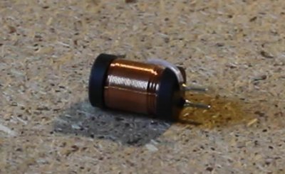
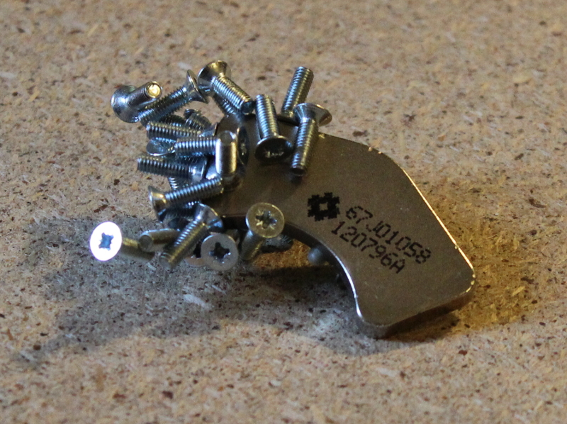
Что такое магнит известно всем — это тело, обладающие собственным магнитным полем, с двумя полюсами намагниченности, способное притягивать металлические предметы.

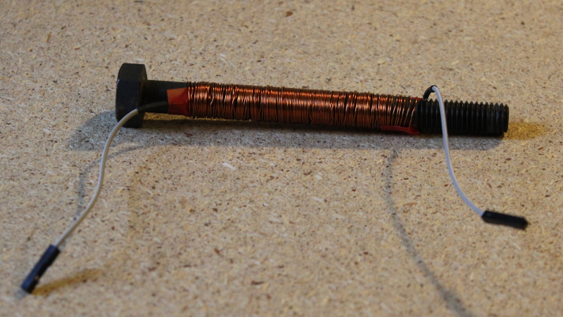
Вокруг провода, по которому течёт электрический ток тоже возникает магнитное поле. Если провод спирально намотать на металлический стержень и подать питание, то стержень превратится в магнит и будет притягивать металлические предметы.
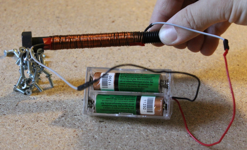
Этот принцип и используется в реле.
Внутри электромагнитных реле находится металлический сердечник — катушка. Над ним устанавливается пластина (подвижный якорь), к которой крепятся от одного до нескольких контактов. Напротив закрепленных контактов устанавливают парные им неподвижные контакты.
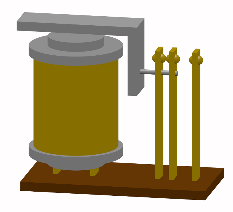
При прохождении электрического тока по виткам сердечника, в нём возникают электромагнитные силы, притягивающие якорь.
В зависимости от конструкции реле, происходит размыкание или замыкание контактов.
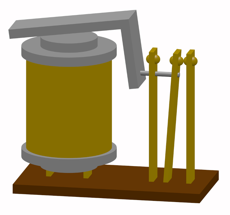
При отключении напряжения якорь возвращается в исходное положение, благодаря пружине.
Таким образом, реле имеет два несимметричных состояния — нерабочее состояние — при обесточенной обмотке, а рабочее — при поданном на обмотку токе.
Нормально замкнутые контакты — это контакты, которые в нерабочем состоянии замкнуты, нормально разомкнутые — в нерабочем состоянии разомкнутые.
Реле даёт возможность включать или выключать приборы питаемые током различной мощности.
Попробуем собрать схему.
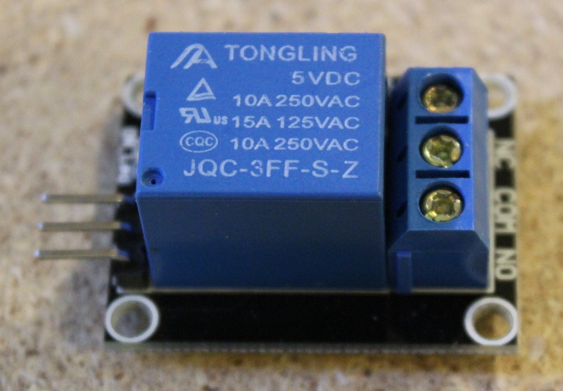
Для демонстрации мы выбрали два реле. Первое — это релейный модуль JQC-3FF для Arduino.
Нам понадобится блок с двумя батарейками на 1.5V каждая, мотор постоянного тока, плата Arduino NANO, и проводочки, у которых один конец припаян к штырьку, второй к контактному разъёму.
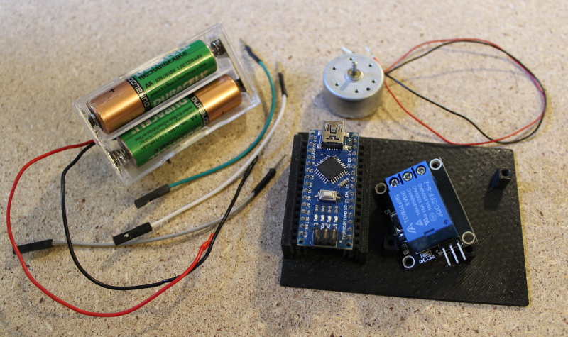
Схема соединения такая.
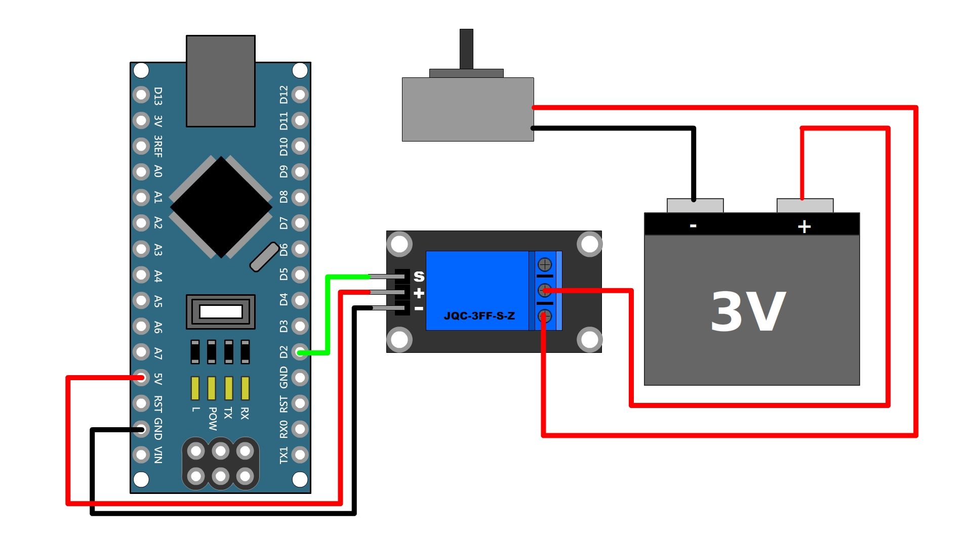

Затем подключаем плату Arduino NANO к компьютеру, открываем среду разработки программ под Arduino, указываем в выпадающем списке «Инструменты» тип платы — Arduino NANO и нужный порт.
Затем загружаем в плату программу, которая включает мотор на 5 секунд, затем на 5 секунд выключает.
void setup() <
pinMode(LED_ON, OUTPUT);
digitalWrite(LED_ON, LOW);
>
void loop() <
// включаем диод
digitalWrite(LED_ON, HIGH);
// задержка на 5 сек
delay(5000);
// выключаем диод
digitalWrite(LED_ON, LOW);
// задержка на 5 сек
delay(5000);
>
Если мы отключим питание от платы Arduino, то выключится и вторая цепь — с мотором. Но есть и другие типы реле, например бистабильное или импульсное. Посмотрим разницу.
Рассмотрим в качестве примера бистабильное реле FRT5 — L2 DC5V.
FRT5 — название реле, L2 — означает, что у него две катушки, DC5V — означает, что реле требуется питание постоянным электрическим током в 5 Вольт.
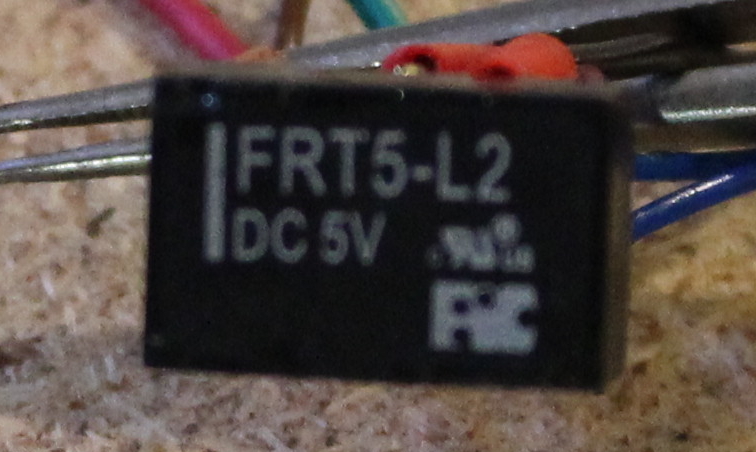
Чтобы замкнуть контакты, надо подать управляющий импульс, чтобы разомкнуть ещё один такой же импульс. Поэтому управляющих проводочка два.
Схема реле выглядит так:
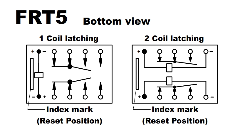
Слева — вариант с одной катушкой, справа — с двумя. Наш вариант тот, что справа.
Мы подключим обычный диод, питаемый двумя батарейками по 1.5V каждая. Через плату Arduino мы будем посылать сигнал реле на замыкание-размыкание цепи диод-батарейка.
Нужно собрать такую схему:
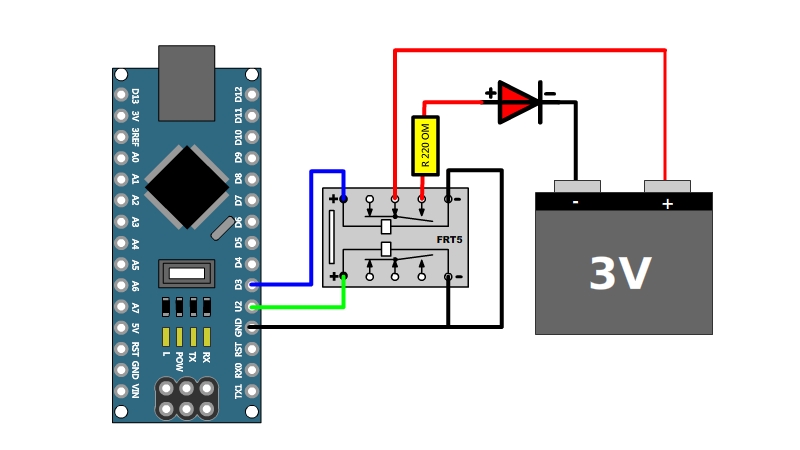
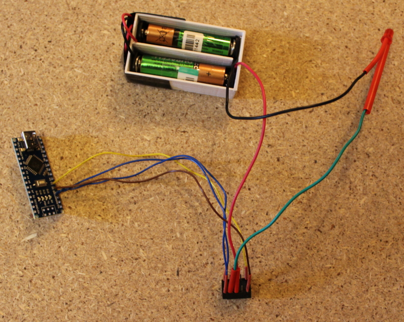
Чтобы замкнуть нормально разомкнутые контакты нужно подать напряжение 5V на контакт D3, а D2 должен быть обесточен. Чтобы разомкнуть эти контакты, выключаем подачу питания на D3 и подаем на D2.
Заливаем в плату Arduino программу и диод начинает мигать раз в секунду.
/*целочисленная константа, которой присваивается значение 3го контакта, отвечающего за замыкание контактов отвечающих за включение диода*/
const int LED_ON = 3;
/*целочисленная константа, которой присваивается значение 3го контакта, отвечающего за размыкание контактов отвечающих за включение диода*/
const int LED_OFF = 2;
void setup() <
pinMode(LED_ON, OUTPUT);
digitalWrite(LED_ON, LOW);
pinMode(LED_OFF, OUTPUT);
digitalWrite(LED_OFF, LOW);
>
void loop() <
// включаем диод
digitalWrite(LED_OFF, LOW);
digitalWrite(LED_ON, HIGH);
// задержка на 1 сек
delay(1000);
// выключаем диод
digitalWrite(LED_ON, LOW);
digitalWrite(LED_OFF, HIGH);
// задержка на 1 сек
delay(1000);
>
Если мы разъединим плату Arduino c питанием во включённом состоянии диода, диод так и останется включённым, так как управляемая цепь была включена в момент выключения управляющей цепи. Если разъединить плату Arduino c питанием при выключенном состоянии – диод будет выключен.
Добавим в схему провод, который будет считывать состояние реле и если при подаче питания на плату Arduino провод регистрирует включённую лампочку, то она должна выключаться.
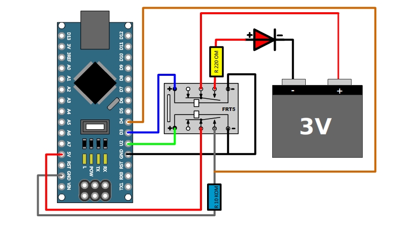
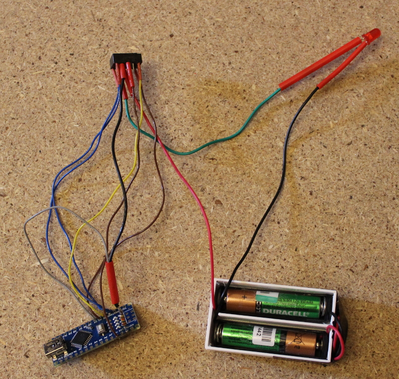
void setup() <
pinMode(LED_ON, OUTPUT);
pinMode(LED_OFF, OUTPUT);
pinMode(LED_TEST, INPUT);
if( digitalRead(LED_TEST) == HIGH )
<
digitalWrite(LED_ON, LOW);
digitalWrite(LED_OFF, HIGH);
>
delay(3000);
>
void loop() <
// включаем диод
digitalWrite(LED_OFF, LOW);
digitalWrite(LED_ON, HIGH);
// задержка на 3 сек
delay(3000);
// выключаем диод
digitalWrite(LED_ON, LOW);
digitalWrite(LED_OFF, HIGH);
// задержка на 3 сек
delay(3000);
>