Сказ о том, как я почистил дроссельную заслонку, клапана PCV и EGR (13.03.16)
Привет Всем.
Так как машинка у меня недавно, не знал какое состояние у дросселя, решил туда заглянуть, предварительно запасься очистителем.
Демонтаж особого труда не доставляет — снять входной патрубок, ресивер… (да и не забываем откинуть минусовую клемму от аккумулятора)
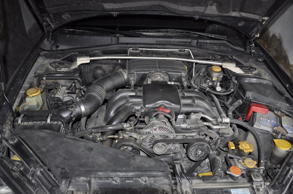
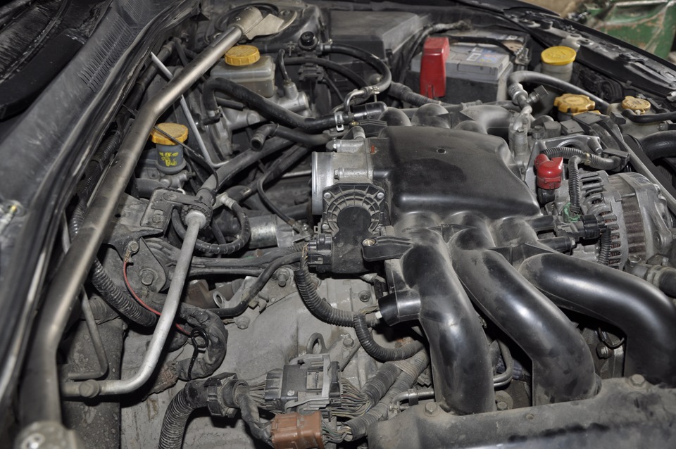
Далее отсоединяем от дросселя два шланга подачи антифриза (очень плотно сидят, как будто прикипели), вытечет буквально пару капель. Потом откручиваем четыре болта головкой на 10 и он у нас в руках.
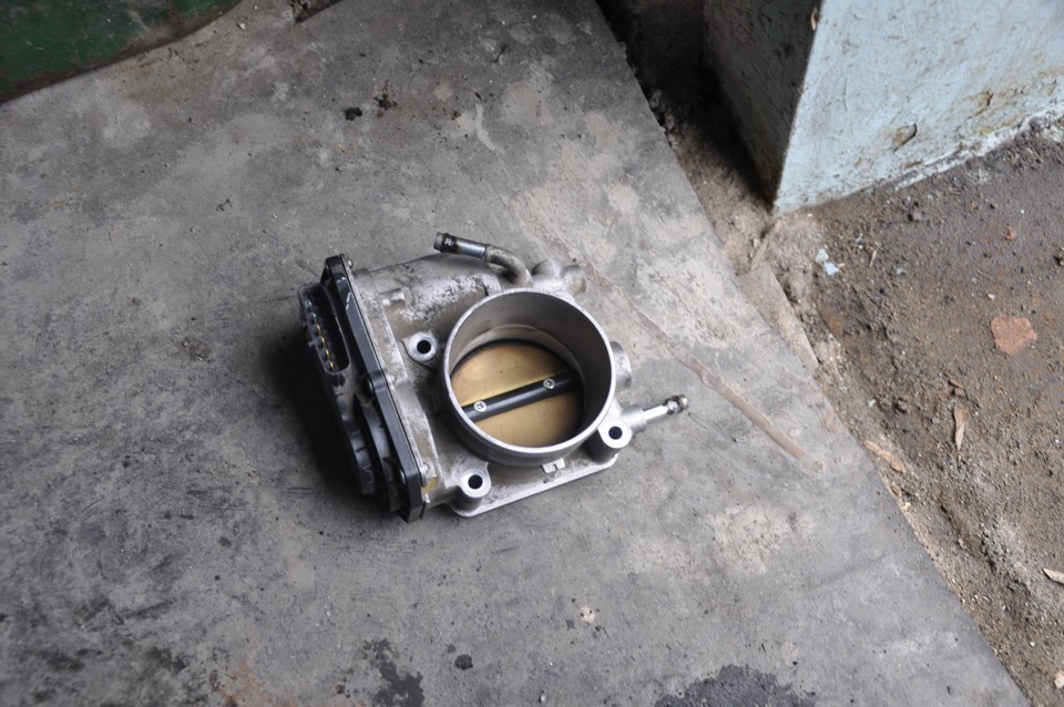 до очистки №1
 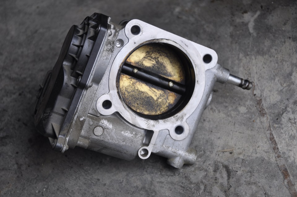 до очистки №2
Я ожидал худшего, что в принципе меня обрадовало. На стенках был нагар, почистил все насколько это возможно
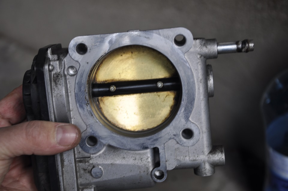 После очистки №1
 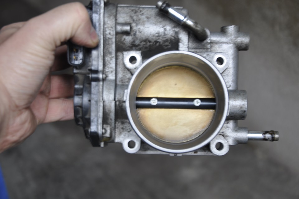 После очистки №2
Все собрал, установил, включил зажигание, подождал сенд 30 и запустил, проверил все сканером нет ли ошибок — все чисто.
Далее самое интересное…
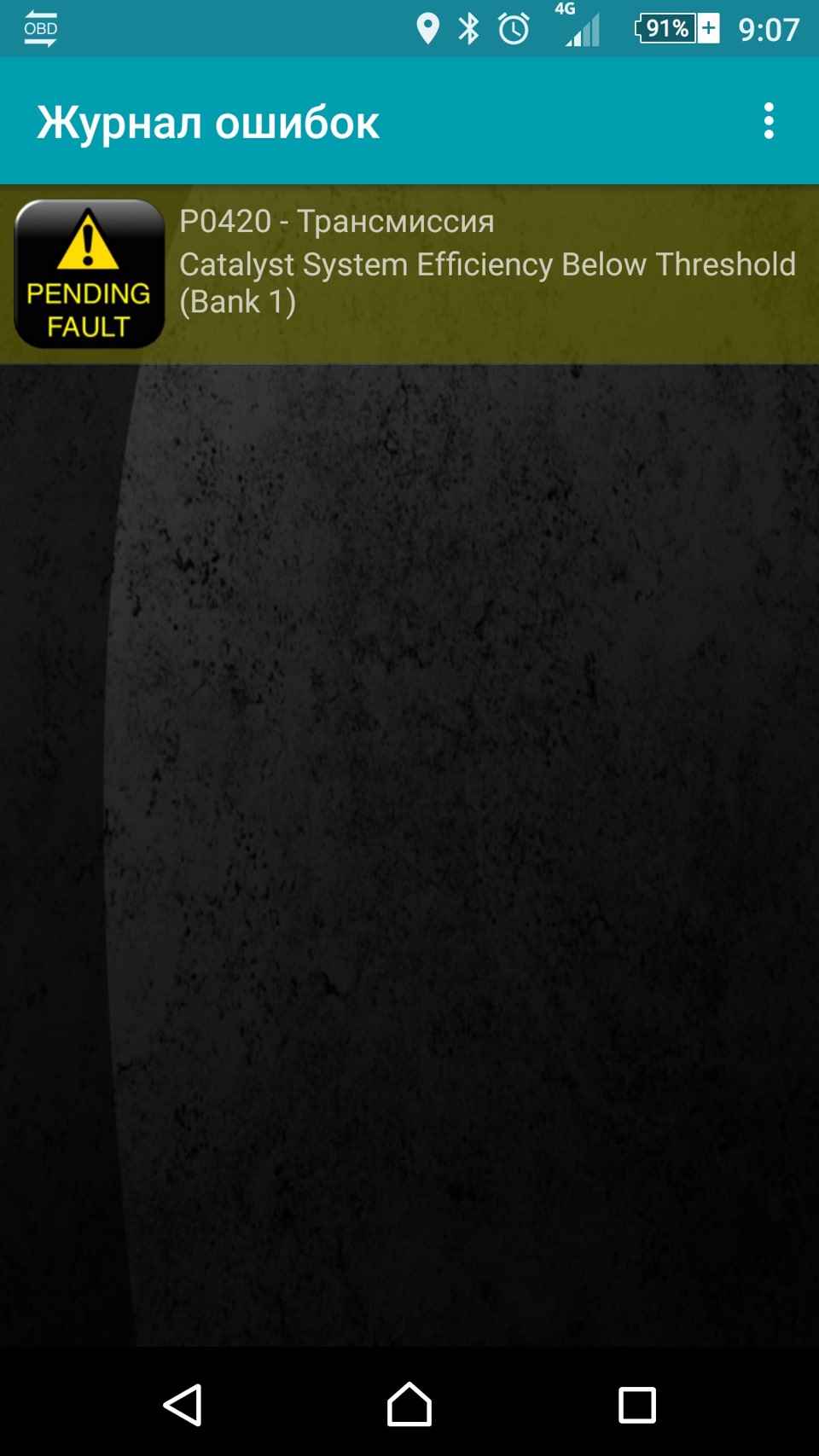
На следующий день поехал по делам. Еду по трассе, чувствую машину подергивает. Скидываю на нейтралку и вижу как обороты "прыгают". Подключаюсь и вижу ошибку
Захожу в результаты испытаний, а там
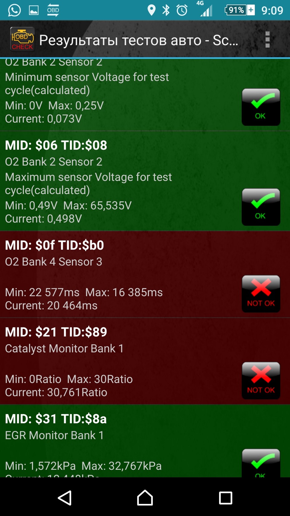 Здесь по Bank 4 Sensor 3 это старая ошибка
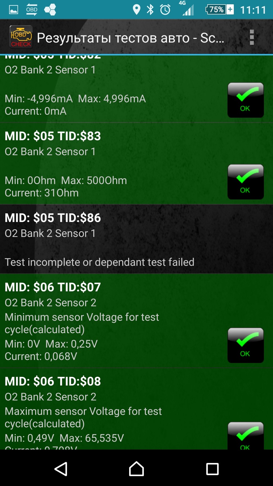
Останавливаюсь, скидываю ошибку (на приборке кстати ничего не вылезло). Захожу опять в результаты, а там почти все "черное" — это не фоткал. Ну думаю почистил заслонку))). Сразу полезли мысли, что сенсоры забились те которые до катов стоят…
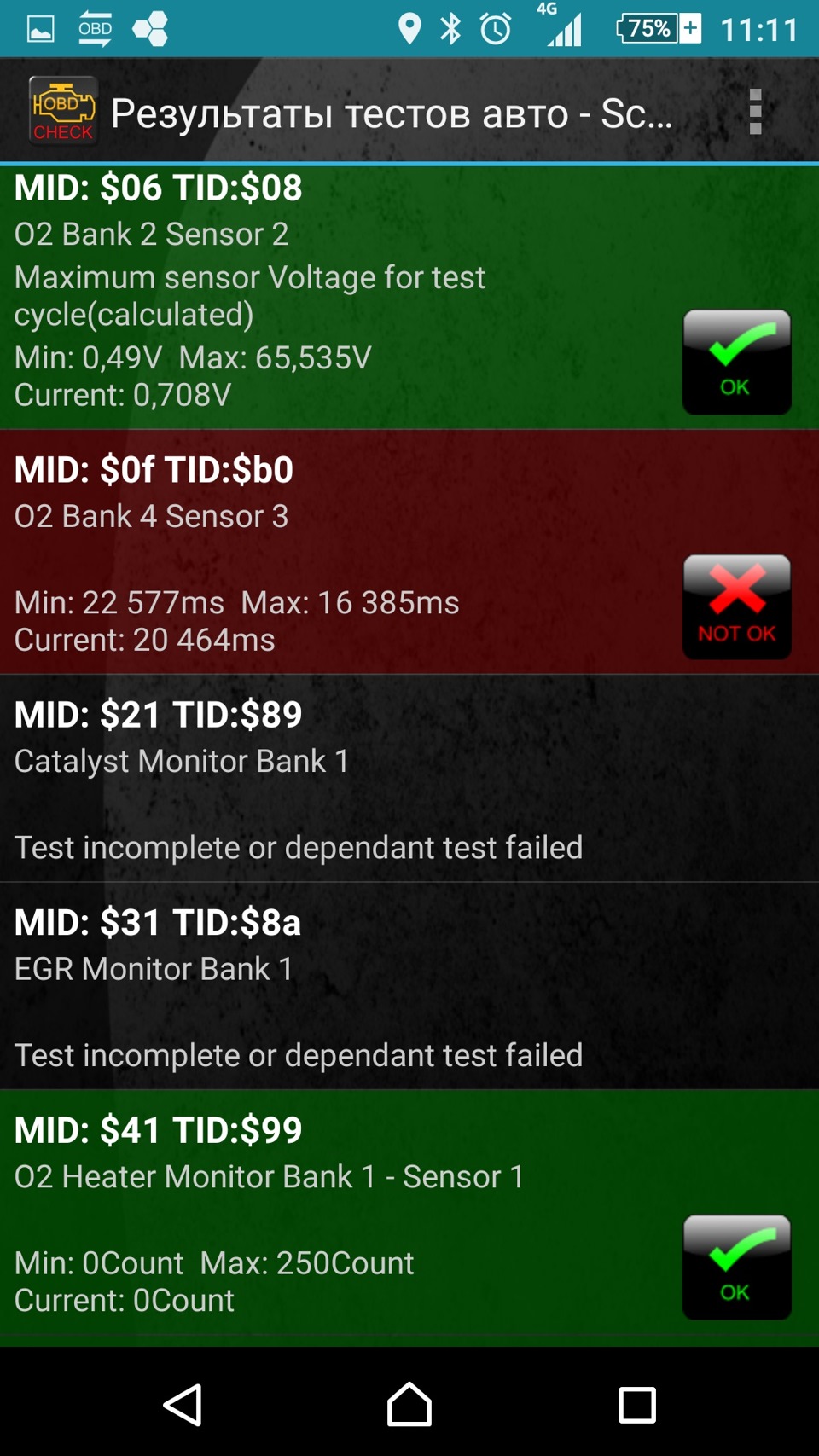
Вообщем поехал я дальше, обороты уже перестали "прыгать" и периодически мониторя "испытания" замечаю, что "зеленого" цвета становится больше. Как добрался до дома остались только "Catalyst Monitor Bank 1" и "EGR Monitor Bank 1". Увидев заветную аббревиатуру "EGR" решил заглянуть туда.
Предварительно искал на драйве бортовики тех, кто их чистил, с этим разобрался. Теперь возник вопрос, где он находится). Практически у всех были записи по 4-х цилиндровым моторам. Ну думаю сам буду искать, как выглядит знаю. Искал наверно минут 20. Находится он в такой Ж… — под впускным коллектором. Фото не делал, на схеме вот где он
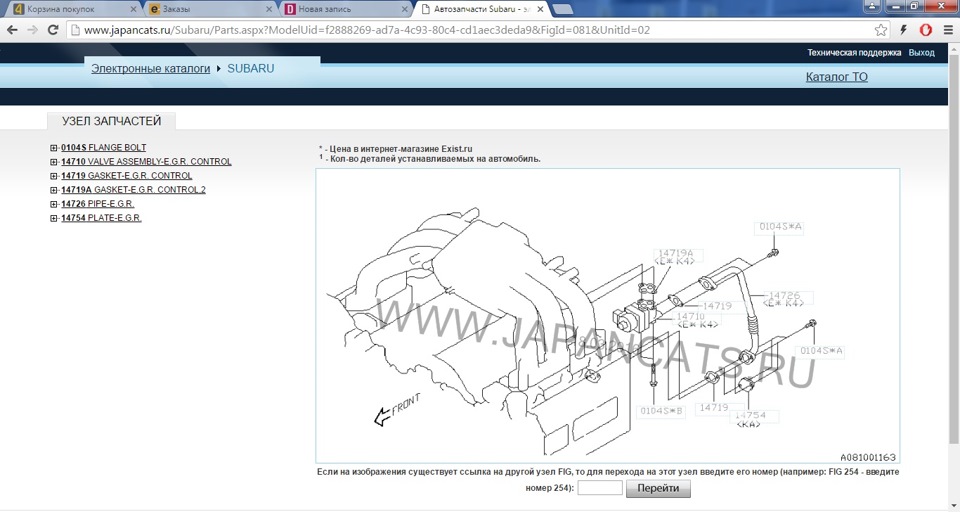 Т.е., если смотреть по ходу движения, то слева
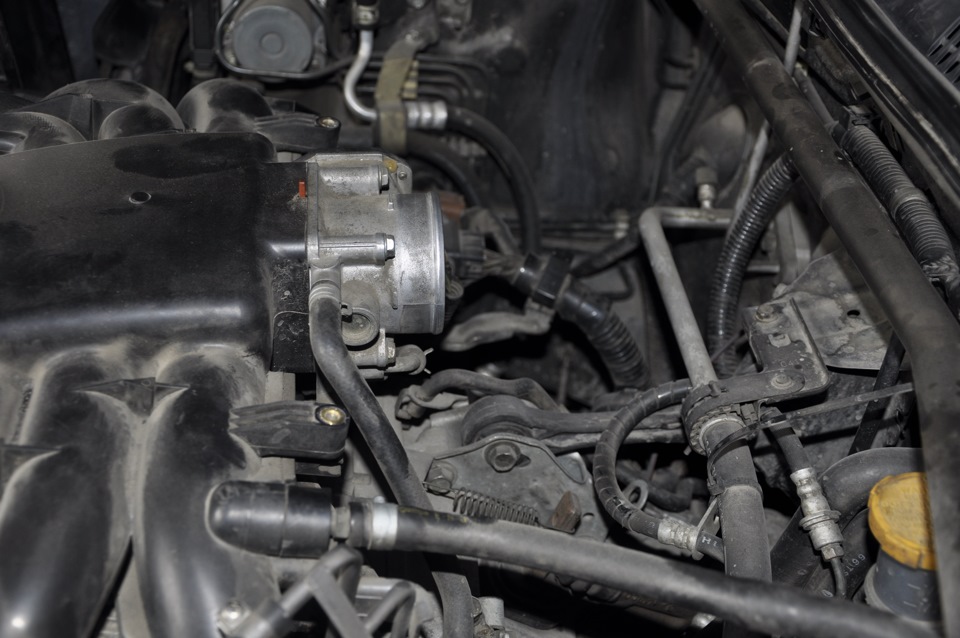
Чтобы до него добраться по хорошему надо снимать впускной коллектор, если пойти трудным путем, то достаточно снять дроссельную. Далее необходимо открутить четыре болта на 12 на впуске и на выпуске клапана. Сразу говорю, что это делать очень неудобно, пространство для "маневров" очень ограниченно, я пока это сделал исцарапал и изодрал себе всю руку. Там два болта, которые вкручены вертикально срывал ключиком, а потом уже трещеточкой докрутил. Потом нужно еще отсоединить от него фишку, эх нелегко это было.
Не очень то и грязный он был. На впуске и на выпуске промыл. На герметичность проверил налив на минут 5 в камеру карба и смотрел не течет ли с другой стороны, также в другую залил. Ниже фото
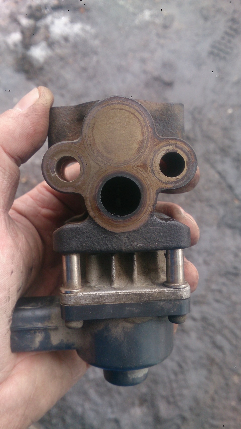 После чистки №1
 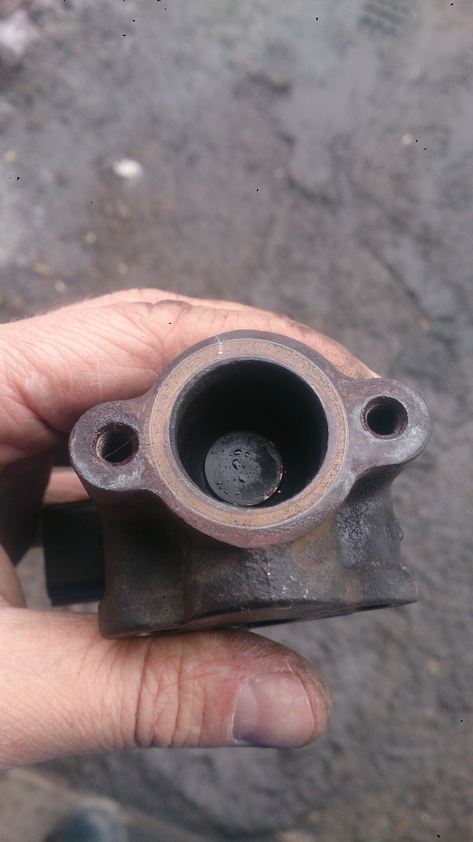 После чистки №2
Установка производилась в обратной последовательности, сначала фишку накинул и т.д.
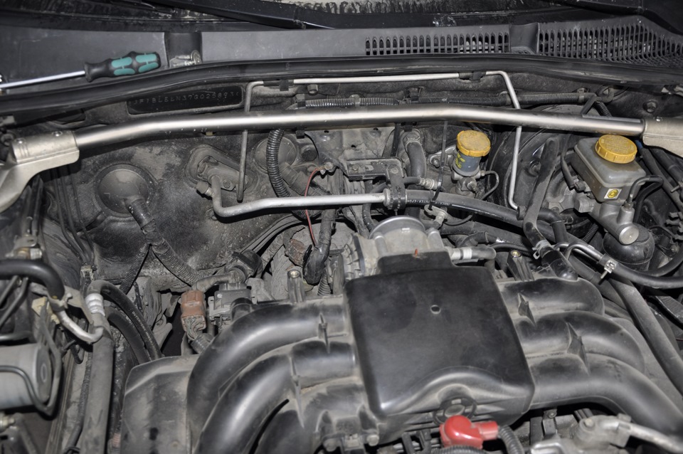
По "пути", так скажем решил заглянуть в клапан PCV, он находится сверху, рядом с левой клапанной крышкой. Для доступа к нему нужно снять аккумулятор, далее снять шланчик. Т.к. у меня уже был опыт с отсоединением этого шланга от клапана только на другом авто, то я подозревал, что он может быть задубевшим и обламаться. И что вы думаете, так и произошло))). Обломился у самого основания клапана
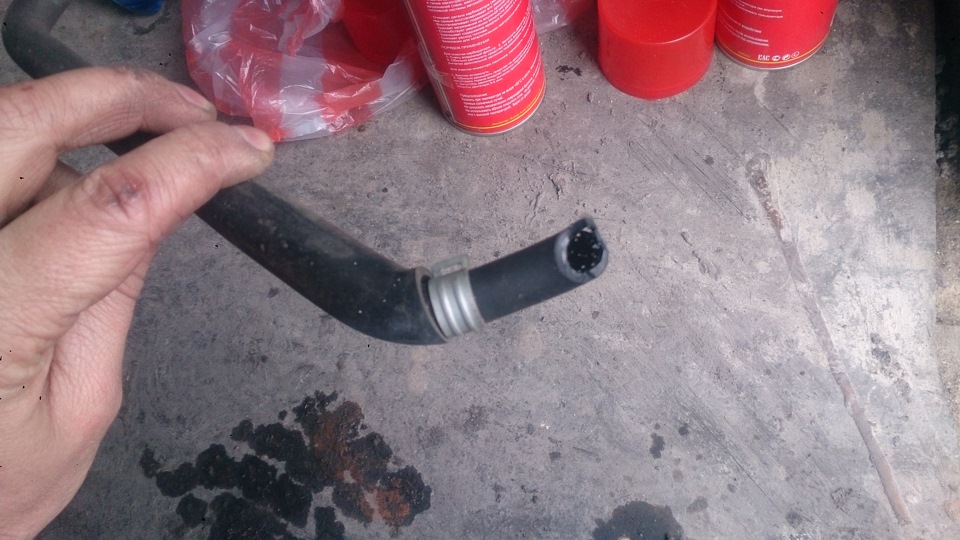
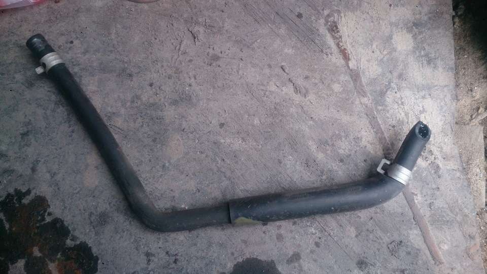
Далее трещоткой с удилинителем и с удлиненной головкой на 19, выкручиваем его, промываем и опять же проверяем на герметичность — должен в одну сторону продуваться, а в другую нет (постов об этом много как должен работать). Мой меня подвел — продувается. Чистил, чистил его не помогает, вообщем данная деталька под замену и шланг к нему же. Т.к. в наличии их не нашлось, то в заказ.
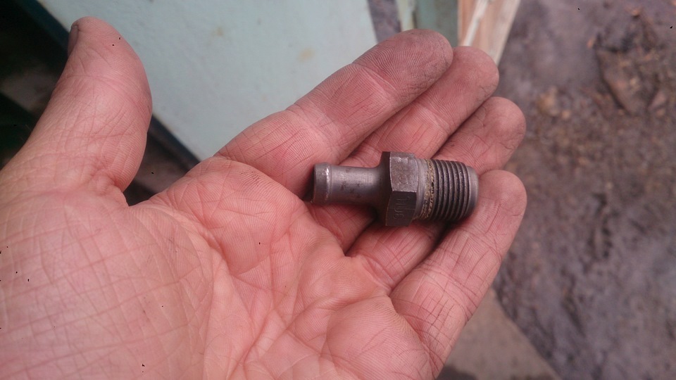 Клапан PCV #1
 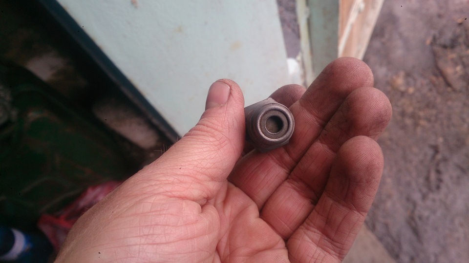 Клапан PCV #2
 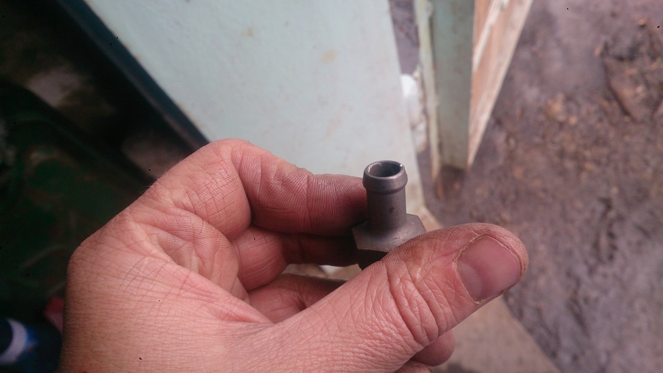 Клапан PCV #3
Клапан пока установил обратно, пока не придет другой, шланг подобрал в ближайшем автомагазине. Конечно шланг можно было и не заказывать, а оставить этот (он толще и бесформенный), просто не хочу колхозить в подкапотном)). Как говорится не по феншую).
На данный момент все ошибки ушли.
Шланчик 11815-AB490 — 978 руб.(4892 тг.)
Клапан PCV 11810-AA100 — 847 руб.(4239 тг.)
Egr monitor bank 1 что это
Что такое Банк 1 и Банк 2, Датчик 1 и Датчик 2 (Bank 1, Bank 2, Sensor 1, Sensor 2)
Вы пытаетесь выяснить, какой датчик кислорода (ДК) действительно нужно заменить? Мы получаем много вопросов о том, как определить, какой ДК является банком 1, а какой — банком 2.
Вот почему мы решили написать эту статью, чтобы раз и навсегда разобраться. Это звучит очень запутанно со всеми этими «Банк 1 Датчик 2 и т. д.». Но если вы разберётесь с этим один раз, это будет не так сложно.
Часто встречаются люди, которые заменили неправильный датчик, потому что они не знали, какой нужно было менять. После того, как вы прочтёте эту статью, вы не будете делать ту же ошибку!
Что такое банк 1 и банк 2?
Цилиндры двигателя часто делятся на две части. Если у вас V-образный двигатель, значит есть один блок на каждой стороне двигателя. Есть много неверной информации о том, какая сторона является банком 1 и 2.

Правда заключается в том, что вы не можете упростить это и сказать, что банк 1 находится на стороне водителя или наоборот, потому что разные двигатели могут иметь 1 цилиндр с разных сторон.
Банк 1 является стороной с цилиндром № 1 (цилиндры 1 − 3 − 5 − 7 и т. д.)
Банк 2 является стороной с цилиндром № 2 (цилиндры 2 − 4 − 6 − 8 и т. д.)
Чтобы узнать, как определить, какая сторона является банком 1 и банком 2, продолжайте читать далее, и мы объясним, как можно легко её найти. Вы можете спросить: но у меня рядная шестёрка, что вы скажете мне насчёт банка 2?
Вот почему мы не хотим говорить вам о стороне, которая является банком 1 и 2. У вас может быть банк 2 как на рядных, так и на поперечных двигателях (двигатели установлены в другом направлении).
Если вы знаете, какой из цилиндров является первым, то нет никакой разницы, какой у вас двигатель. Bank 1 всегда находится на цилиндре 1 − 3 − 5 − 7 − 9 − 11, а bank 2 всегда на цилиндре 2 − 4 − 6 − 8 − 10 − 12.
Что такое датчик 1 и 2?
Номер датчика говорит нам о том, где на выхлопной системе установлен датчик кислорода или датчик температуры выхлопных газов. Первый датчик расположен ближе к двигателю, а второй — сзади выхлопной системы.
Вообще, если мы говорим о ДК:
Датчик 1 = передний перед каталитическим нейтрализатором (ДК выше по потоку).
Датчик 2 = задний после катализатора (ДК ниже по потоку).
Некоторые дизельные двигатели имеют много датчиков температуры выхлопных газов, и в них могут использоваться датчики 1 − 2 − 3 − 4 и т. д. В этих случаях датчик 1 расположен ближе всего к двигателю, а последний датчик находится в конце выхлопной системы.
Как найти номера цилиндров?
Найти номер цилиндра можно несколькими способами. На некоторых автомобилях номер цилиндра выбит на крышке картера.
Если у вас есть высоковольтные провода зажигания, на них также часто встречаются цифры. Но это нерекомендуемый метод, поскольку раньше их могли менять или переносить между цилиндрами.

Самый безопасный способ — это посмотреть крышке картера или найти номера цилиндров в руководстве по ремонту/обслуживанию автомобиля. Можно позвонить автодилеру и спросить их. Можно попытаться найти информацию в Интернете, выполнив поиск по коду вашего двигателя.
Рекомендация механиков
Если у вас есть сканер или адаптер OBD2, вы можете сделать всё намного проще.
- Подключите OBD2 сканер и сотрите коды неисправностей.
- Убедитесь, что все коды неисправностей удалены.
- Отключите один датчик кислорода и считайте код появившейся ошибки. Теперь вы увидите, где банк 1, а где банк 2.
Используя этот метод, вы будете на 100% уверены, что замените нужный датчик.
У меня ошибка P0420, что я должен исправить в первую очередь?
Код P0420 может быть вызван неисправным датчиком кислорода. Мы рекомендуем сначала устранить неисправность ДК, так как это может исправить ошибку P0420.
Проверьте, нет ли утечек выхлопных газов, которые могли бы вызвать код ошибки P0420 и лямбда-зонда.
Клуб Любителей SsangYong New Actyon (СсангЙонг Нью Актион): Самостоятельная диагностика (ELM 327)
- (6 Страниц)

- 4
- Добавить в избранное
- Вы не можете создать новую тему
 Тема закрыта
 Alexgeodez
- Группа: Заслуженные Сангйонгаводы
- Сообщений: 1 618
- Регистрация: 19 декабря 11
- На счете: 112,2 рублей
- Автомобиль : SsangYong New Actyon
- Пол: Мужчина
- Город: Ногинск
- Интересы: Семья, рыбалка
Когда с телефона туда захожу, то по русски там написано, допустим положение дроссельной заслонки, а когда начинаешь разбирать сохраненные журналы/логи, то там уже написано сенсор 7 банк 1, и.т.д., если бы он сохранял так как на мониторе, то вопрос по сенсорам бы не озвучивался, а так сопоставлять придется. что да откуда. (скрины с телефона тоже не хочет сохранять, только логи. ) Да и не уверен я что значения от и до он правильные пишет.
Пример: допустим мин — 30000, макс — 10000, сейчас — 850 как итог ошибка. (как минимум может быть больше максимума? ) И таких показаний около 4-5!
Serg1
- Группа: Уважаемые Сангйонгаводы
- Сообщений: 680
- Регистрация: 05 августа 12
- На счете: 270,3 рублей
- Автомобиль : SsangYong New Actyon
- Пол: Мужчина
- Город: Москва
- Интересы: Разные.
Alexgeodez
- Группа: Заслуженные Сангйонгаводы
- Сообщений: 1 618
- Регистрация: 19 декабря 11
- На счете: 112,2 рублей
- Автомобиль : SsangYong New Actyon
- Пол: Мужчина
- Город: Ногинск
- Интересы: Семья, рыбалка
Serg1
- Группа: Уважаемые Сангйонгаводы
- Сообщений: 680
- Регистрация: 05 августа 12
- На счете: 270,3 рублей
- Автомобиль : SsangYong New Actyon
- Пол: Мужчина
- Город: Москва
- Интересы: Разные.
Vzapase

- Группа: Уважаемые Сангйонгаводы
- Сообщений: 507
- Регистрация: 29 марта 12
- На счете: 417,9 рублей
- Автомобиль : SsangYong New Actyon
- Пол: Мужчина
- Город: Москва
- Интересы: Дача
Колеги!
Может кто подскажет протокол для дизеля?
Мне так и не удалось победить свой девайс. Попробовал три программы — ноль. У сына на Ауди А4 попробовал — тоже ноль.
Программа девайс видит, подключается, проверяет протоколы — и на этом все
Serg1
- Группа: Уважаемые Сангйонгаводы
- Сообщений: 680
- Регистрация: 05 августа 12
- На счете: 270,3 рублей
- Автомобиль : SsangYong New Actyon
- Пол: Мужчина
- Город: Москва
- Интересы: Разные.
serg1476

- Группа: Оргкомитет
- Сообщений: 2 555
- Регистрация: 01 июня 11
- На счете: 1209,9 рублей
- Автомобиль : SsangYong New Actyon
- Пол: Мужчина
- Город: Мытищи
- Интересы: Семья
Vzapase
- Группа: Уважаемые Сангйонгаводы
- Сообщений: 507
- Регистрация: 29 марта 12
- На счете: 417,9 рублей
- Автомобиль : SsangYong New Actyon
- Пол: Мужчина
- Город: Москва
- Интересы: Дача
 serg1476 (05 марта 2013 — 13:37) писал:
Наверно так и сделаю
А пробовал OBDавто доктор, ScanMasterLite, Torque (free)
Alexgeodez
- Группа: Заслуженные Сангйонгаводы
- Сообщений: 1 618
- Регистрация: 19 декабря 11
- На счете: 112,2 рублей
- Автомобиль : SsangYong New Actyon
- Пол: Мужчина
- Город: Ногинск
- Интересы: Семья, рыбалка
Сообщение отредактировал Alexgeodez: 06 марта 2013 — 07:41
Vzapase
- Группа: Уважаемые Сангйонгаводы
- Сообщений: 507
- Регистрация: 29 марта 12
- На счете: 417,9 рублей
- Автомобиль : SsangYong New Actyon
- Пол: Мужчина
- Город: Москва
- Интересы: Дача
Alexgeodez (06 марта 2013 — 07:38) писал:
Rulzen

- Группа: Продвинутые
- Сообщений: 67
- Регистрация: 10 февраля 12
- На счете: 103,5 рублей
- Автомобиль : SsangYong New Actyon
- Пол: Мужчина
- Город: Москва
- Интересы: Авто, мото, вело, фото,
е..ля, гребля и охота
Не секрет, что полноценного бортового компьютера на актёне нет
Выйти из этой ситуации можно очень легко и бюджетно
(В эксперименте участвовали Actyon "175лс, дизель", дешёвый китайский elm 327 Bluetooth, Samsung galaxy tab 6200)
Вот его описание http://www.elm327.dash-pc.ru/
Лучше с блютусом или вайфаем. Очень удобно — никаких проводов.
Также понадобится телефон или планшетник на андроиде, желательно с экраном побольше, т.к. полезной информации которую можно вывести на экран довольно много.
И, самое главное, нужна программа для связи с адаптером. В моём случае это Torque pro
http://androidoz.com/ru/torque-pro/
Программа платная, 155р. Качается с плей-маркета. Почти весь контекст на русском языке.
Для современного человека с переводом проблем не будет.
Есть и бесплатная версия торки, но сильно урезаная. Я её использовал только для проверки работоспособности адаптера. Потом купил официалку. Деньги списали со счёта Билайн, буквально за два клика
Всё очень просто! Адаптер ELM327 присоединяется к диагностическому порту, который находится над педалями. Разъём "смотрит" прямо вниз. Он там один, не перепутаете.
Вставляете адаптер в разъём, слегка прижимаете для надёжности. На адаптере загорится красная лампочка, даже при выключенном зажигании.
Теперь берёте планшет, включаете блютус, ищете адаптер (у меня он назывался "OBD"), сопрягаете устройства. Пароль на добавление может быть "0000" или "1234" или "5678".
И так: Адаптер установлен, блютус включен, устройства друг друга видят. Можно идти дальше.
Включаете зажигание. Заводить авто не обязательно.
Запускаете торку (Torque pro или Lite).
Если всё в порядке, то программа увидит адаптер.
В моём случае пришлось поиграться с настройками подключения, т.к. торка теряла адаптер каждые 3-4мин, при том, что планшет держал блютус-соединение неразрывно.

Сигнализация на начало прожига сажевого фильтра.
Заходите в главные настройки, дальше уведомления/предупреждения (Alarms). Добавляете новое предупреждение. Датчик — "Температура катализатора датчик 1 банк 1", значение 500, максимум. Окей.
При обычном режиме до 500 градусов катализатор не раскаляется, 500 пока вполне достаточно.
Есть там ещё один датчик "Температура катализатора датчик 2 банк 1". На сколько я понял, он находится после катализатора и температура там всегда выше чем на первом.
При первом же прожиге телефон начал пищать, сигнализируя о начале прожига.
Остальные "алармы":
Также я установил предупреждения на падение напряжения в бортовой сети (есть ещё напряжение на самом адаптере, я его не использовал) ниже 12 вольт.
На повышение температуры охлаждающей жидкости выше 100 градусов цельсия.
Можно установить и другие алармы, датчиков на актёне несколько десятков. Но я пока не замарачивался.
В главном меню нажимаете жёлтую иконку "чек инджайн". Запускаете процесс сканирования.
Будут показаны все ошибки, когда либо появлявшиеся на машине и зажигавшие ненавистную лампочку "чек инджайн", если конечно, эти ошибки не тёрли сервисмены. Например, после замены датчика выпускного коллектора эту ошибку мне потёрли.
И так, если ошибки были, и торка их увидела и вывела на экран, сохраните журнал, чтобы если что, всегда можно было посмотреть их коды, даже при не подключенном адаптере.
Там же, в меню, и управление ошибками. Можно их стирать, но учтите, что, возможно, они могут понадобиться для гарантийного ремонта!!!
Если код ошибки стандартный, то торка сразу выводит расшифровку, увы, на английском. Если не известен, то можно её записать и потом "нагуглить" в яндексе )))
Коды основных ошибок и их русская расшифровка находятся в прикреплённом вордовском файле.
On-Board Diagnostics (OBD) – introduction to the Modes of Operation (Diagnostic Services)
The vast majority of vehicles in use nowdays are OBD compliant, which means that they have on-board monitoring functions for the systems and components whose functionality has an impact on exhaust gas toxic emissions levels.
For an overall understanding of OBD read the article Introduction to On-Board Diagnostics (OBD).
The communication between the scantool (diagnostic equipment) and the vehicle is defined in the OBD related standards. The communication protocol and the content of the diagnostic data is define in the Application Layer (OSI Level 7).
In this article, we are going to focus on the diagnostic modes/services defined for the CAN protocol. The diagnostic modes/services are described in the ISO and SAE standards:
- ISO 15031-5: Road vehicles – Communication between vehicle and external equipment for emissions-related diagnostics – Part 5: Emissions-related diagnostic services
- SAE J1979: E/E Diagnostic Test Modes
Currently, on the market there are three main types of diagnostic devices (scantools, testers):
- handheld
- PC/laptop based
- mobile device (phone or tablet) application

Image: OBD Scantool
The handheld one is the one usually identified as a scantool. It’s an independent device, which doesn’t need to be powered from an external source, because it’s using the OBD connector supply voltage pins. It can be used regardless of the type of the vehicle, as long as both are OBD 2 compliant. The advantage of the handheld scantool is that it’s portable and easy to use, just “plug and play”.

Image: Windows OBD Scantool
Credit: Auterra
The PC/laptop based “scantool” is basically a software that uses an external interface to connect to the vehicle’s OBD port. The main disadvantage, compared to the handheld one, is that you need a laptop with an operating system to install and use the diagnostic software. Further, it still requires an OBD adapter (also called “interface”), which is converting the data between the laptop and vehicle to the right format. The connection between the OBD adapter and the laptop can be serial (USB or RS-232 port) or wireless (Bluetooth).
The advantage of this diagnostic device is mainly linked to the memory and data processing power of the laptop/PC. Large amounts of data can be logged and stored, data plots and other functions (acceleration time, fuel consumption, etc.) can be integrated into the main application.

Image: OBD diagnostic device – mobile
Credit: PLX Devices
The third type, the mobile device “scantool”, can be regarded as a combination between the handheld solution and the PC/laptop based one. It still requires the use of an OBD adapter between the mobile device and vehicle but has the advantage of portability. Most of these devices are using a wireless connection (Bluetooth) for the OBD adapter.
Regardless of the type of diagnostic device, the OBD modes of operation (also called diagnostic services) define how the data is requested from the vehicle and how the vehicle responds to the request. You can look at the OBD modes of operation as a definition of the “language” to be used by both parties (scantool and vehicle) when requesting and sending data.
The communication between diagnostic device (scantool) and vehicle is client-server type, based on request and response.

Image: OBD mode of operation (diagnostic services) client-server type
The Client is defined as the function that is part of the diagnostic device (scantool, tester), that makes use of the diagnostic services. A tester normally makes use of other functions such as data base management, specific interpretation and man-machine interfaces.
The Server is defined as a function that is part of an electronic control unit on-board of the vehicle and that provides data to the diagnostic services.
The diagnostic Service can be defined as an information exchange initiated by a client (external test equipment) in order to require diagnostic information from a server (ECU) or/and to modify its behavior for diagnostic purpose.
In the OBD CAN protocol there are 9/10 modes of operation (diagnostic services), each defined by an identifier (also called header). First 9 modes of operation are common between ISO and SAE standards, the 10 th is specific to the SAE standard.

Image: OBD modes of operation (diagnostic services)
The table below describes the purpose of each mode of operation (diagnostic service) and which standard contains it. Even if there are different standard defining the diagnostic services (SAE and ISO), the content is similar, the ISO standards being adapted after the SAE ones.
| Diagnostic service Mode of operation |
Description | Standard |
| $01 | Request Current Powertrain Diagnostic Data | SAE, ISO |
| $02 | Request Powertrain Freeze Frame Data | SAE, ISO |
| $03 | Request Emission-Related Diagnostic Trouble Codes | SAE, ISO |
| $04 | Clear/Reset Emission-Related Diagnostic Information | SAE, ISO |
| $05 | Request Oxygen Sensor Monitoring Test Results | SAE, ISO |
| $06 | Request On-Board Monitoring Test Results for Specific Monitored Systems | SAE, ISO |
| $07 | Request Emission-Related Diagnostic Trouble Codes Detected During Current or Last Completed Driving Cycle |
SAE, ISO |
| $08 | Request Control of On-Board System, Test or Component | SAE, ISO |
| $09 | Request Vehicle Information | SAE, ISO |
| $0A | Request Emission-Related Diagnostic Trouble Codes with Permanent Status | SAE |
The dollar sign “$” in front of the numerical value highlights that this is an identifier. It’s important to know that the numerical values of the identifiers are in hexadecimal format. The correct notations would be using the 0x prefix, for example 0x01 .
Mode/Service $01 – Request Current Powertrain Diagnostic Data
The purpose of this service is to allow the individual who is performing a vehicle diagnostic, to access the current emission-related data values, including analogue inputs and outputs, digital inputs and outputs, and system status information.
The Client request for information includes a Parameter IDentification (PID) value which indicates to the on-board system what specific information is requested. PID specifications (description, scaling information and display formats) are included in the ISO and SAE standard mentioned above.
The electronic control units (Server) shall respond to this message by transmitting the requested data value last determined by the system. This service provides accurate information, all data values returned for sensor readings shall be actual readings, not default or substitute values used by the system (constant values or calibration parameters) due to a fault with the sensor.

Image: OBD Mode 01 – intake air mass flow rate plot
This diagnostic mode can provide relevant data to the user since it gives the current values of the engine parameters (speed, load, temperature, etc.). If the data is requested continuously (e.g. every 0.1 s) and recorded, a data plot can be created, which shows the variation in time of the parameters.
There are currently 135 PIDs defined in the OBD standard but not all of them are mandatory. There are a limited number of mandatory PIDs, the rest of them depending on the configuration of the system (engine).
The table below contains the list of mandatory PIDs (common between spark ignition and compression ignition engines) and some examples of optional PIDs.
| PID | Description | Required |
| 00 | PIDs supported [01 – 20] | Mandatory |
| 01 | Monitor status since DTCs cleared | |
| 02 | DTC that caused required freeze frame data storage | |
| 04 | Calculated LOAD Value | |
| 05 | Engine Coolant Temperature | |
| 0C | Engine RPM | |
| 0D | Vehicle Speed Sensor | |
| 1C | OBD requirements to which vehicle or engine is certified |
|
| 20 | PIDs supported [21 – 40] | |
| 21 | Distance Traveled While MIL is Activated | |
| 30 | Number of warm-ups since DTC cleared | |
| 31 | Distance since DTCs cleared | |
| 0B | Intake Manifold Absolute Pressure | Optional |
| 0F | Intake Air Temperature | |
| 10 | Air Flow Rate from Mass Air Flow Sensor | |
| 1F | Time Since Engine Start | |
| 42 | Control module voltage |
Every parameter is identified with a number, which is in hexadecimal format. For example, the identifier of the engine speed is 0x0C .
For example, let’s assume that we want to read the current value of the calculated engine load. This parameter can be read with the diagnostic service 0x01 and has the identifier 0x04 .
For spark ignition (gasoline) engines, Calculated Load Value is an indication of the current airflow divided by peak (maximum) airflow at Wide Open Throttle (WOT) as a function of rpm, where airflow is corrected for altitude and ambient temperature. This definition provides a unit-less number, and provides the service technician with an indication of the percent engine capacity that is being used. For compression ignition (diesel) engines, the calculated load value shall be determined by replacing air mass flow with fuel mass flow in the calculation.

Image: OBD scantool requesting engine load parameter
The scantool (client) will send 0104 to the vehicle (server). This message has two components, both in hexadecimal format:
- 01 is the ID of the diagnostic service to be used
- 04 is the ID of the requested engine parameter (calculated load in this case)
The vehicle will respond with 41046A . This response message has three components, all in hexadecimal format:
- 41 is the positive response ( 40 + 01 ), which means that the server understand the request and will provide the data
- 04 is an acknowledgement of the parameter ID to be read
- 6A is the value of the calculated engine load
Now the scantool has to convert the hexadecimal value of the engine load in physical value so that it can be understood by the human user. The conversion from hexadecimal to physical values [%] is defined in the ISO and SAE standard for each PID. For the calculated engine load, the conversion is:
To understand what’s happening in the scantool, we’ll convert the hexadecimal number into decimal values. For reference read the article Hexadecimal to Decimal Conversion, use a handheld calculator or a Matlab/Scilab function:
Now we can calculate the physical value of the engine load:
\[\text
The same approach is valid for all of the physical engine parameters.
Mode/Service $02 – Request powertrain freeze frame data
When a monitored component/system fails, a diagnostic trouble code (DTC) is raised. For a better understanding of the failure, by the service technician, the OBD is providing a “freeze frame”. This is a set of engine and vehicle parameters stored in the non-volatile memory, when the DTC is raised.
For example, while driving at high speed, a DTC is raised for the exhaust catalyst. In order to understand why the failure occurred, we are going to have the value of the engine temperature, speed, load and vehicle speed stored in the freeze frame, for the exact moment of the failure appearance.
Example of Freeze Frame Data:
| PID | Description | Value | Units |
| 0x02 | DTC that caused required freeze frame data storage | P1461 | – |
| 0x04 | Calculated Load Value | 0 | % |
| 0x05 | Engine Coolant Temperature | 63 | °C |
| 0x0B | Intake Manifold Absolute Pressure | 89.0 | kPa |
| 0x0C | Engine RPM | 0 | rpm |
| 0x0D | Vehicle Speed | 0 | km/h |
| 0x10 | Air Flow Rate from Mass Flow Sensor | 0.00 | gm/sec |
Only engine or vehicle parameters defined as PIDs can be used in the freeze frame.
Mode/Service $03 – Request Emission-Related Diagnostic Trouble Codes
The purpose of this diagnostic service is to enable the external test equipment (scantool, tester) to obtain all the “confirmed” emission-related diagnostic trouble codes (DTCs). A confirmed fault code is defined as the DTC stored when an OBD system has confirmed that a malfunction exists. Usually, the confirmation is given on the second driving cycle following the malfunction detection.
When the scantool is sending a Service $03 request for all emission-related DTCs, each ECU that has DTCs shall respond with one message containing all emission-related DTCs. If an ECU does not have emission-related DTCs, then it shall respond with a message indicating no DTCs are stored by setting the parameter number of DTC to 0x00 .
Example of Emission-Related Diagnostic Trouble Codes:
| Code | Description |
| P0000 | No stored trouble codes |
| P1462 | A/C pressure sensor circuit voltage high |
| P1461 | A/C pressure sensor circuit voltage low |
Mode/Service $04 – Clear/Reset Emission-Related Diagnostic Information
The purpose of this service is to provide a means for the external test equipment (scantool, tester) to command ECUs to clear all emission related diagnostic information.
Mode $04 clears/erases diagnostic trouble codes and diagnostic data, which includes:
- freeze frames
- inspection/maintainance readiness
- status of monitors
- PID for number of engine warm-ups, distance with Malfunction Indicator Lamp (MIL) ON
- data read by mode/service $06
This mode can be used by the service technicians (or other users) to turn off the MIL and erase stored DTCs after a repair has been performed. It can be also used as a confirmation that the fault is not present anymore (after reset the DTC are read again).
Mode/Service $05 – Request Oxygen Sensor Monitoring Test Results
Mode $05 provides test results for oxygen (lambda) sensors. It is not supported anymore for CAN communication protocol but all the functionality of this mode is implemented in Mode $06.
Mode/Service $06 – Request On-Board Monitoring Test Results for Specific Monitored Systems
The purpose of this diagnostic service is to allow access to the results for on-board diagnostic monitoring tests of specific components/systems that are either continuously monitored (e.g. misfire monitoring) or non-continuously monitored (e.g. catalyst system).
The vehicle manufacturer will define “Manufacturer Defined Test IDs” for different tests of a monitored system. Mode $06 will provide the monitoring test values and fault (malfunction) limits for the defined tests (monitors).
The data provided by this diagnostic service can be used by service technicians to identify which monitor has failed and by how much. Once the failed component/system has been repaired/restored, Mode $06 data can be used to validate the process.
A particular monitoring test of Mode $06 is defined for the oxygen (lambda) sensor. The test monitors the voltage output of the sensor.

Image: OBD Mode 06 – oxygen sensor data
The parameters of the oxygen sensor output voltage are requested as Test ID (TID), with the following description:
| Test ID | Description |
| $00 | ISO/SAE reserved |
| $01 | Rich to lean sensor threshold voltage (constant) |
| $02 | Lean to rich sensor threshold voltage (constant) |
| $03 | Low sensor voltage for switch time calculation (constant) |
| $04 | High sensor voltage for switch time calculation (constant) |
| $05 | Rich to lean sensor switch time (calculated) |
| $06 | Lean to rich sensor switch time (calculated) |
| $07 | Minimum sensor voltage for test cycle (calculated) |
| $08 | Maximum sensor voltage for test cycle (calculated) |
| $09 | Time between sensor transitions (calculated) |
| $0A | Sensor period (calculated) |
| $0B | EWMA (Exponential Weighted Moving Average) misfire counts for last ten (10) driving cycles (calculated, rounded to an integer value) |
Example of Monitoring Test Results (non oxygen sensor):
| OBDMID | Description | Test ID | Description | Value | Min Value | Max Value | Min | Max | Result |
| 0x31 | EGR Monitor Bank 1 | 0x80 | Manufacture test ID description | 21 | -3277 | 217 | -3276.8 | 3276.7 | Passed |
| 0x21 | Catalyst Monitor Bank 1 | 0x80 | Manufacture test ID description | 0 | 0 | 1 | 0 | 1.99 | Passed |
| 0x81 | Fuel System Monitor Bank 1 | 0x82 | Manufacture test ID description | 1 | 1 | 1 | 0 | 1.99 | Passed |
| 0xA4 | Misfire Cylinder 3 Data | 0x0C | Misfire counts for last/current driving cycles | 2 | 0 | 2 | 0 | 65535 | Passed |
Mode/Service $07 – Request Emission-Related Diagnostic Trouble Codes Detected During Current or Last Completed Driving Cycle
The purpose of this diagnostic service is to enable the external test equipment (scantool, tester) to obtain “pending” diagnostic trouble codes (DTCs) detected during current or last completed driving cycle for emission-related components/systems.
A pending fault code is defined as the diagnostic trouble code, stored as a result of initial detection of a malfunction (usually in the current driving cycle), before the activation of the malfunction indicator lamp (MIL).
This operating mode is required for all diagnostic trouble codes and it’s independent of Service $03.
The intended use of this data is to assist the service technician after a vehicle repair, and after clearing diagnostic information, by reporting test results after a single driving cycle.
Example of Emission-Related Pending Diagnostic Trouble Codes:
| Code | Description |
| P0000 | No pending trouble codes |
| P1462 | A/C pressure sensor circuit voltage high |
Mode/Service $08 – Request Control of On-Board System, Test or Component
The purpose of this service is to enable the external test equipment (scantool, tester) to control the operation of an on-board system, test or component. With the help of this service, the service technician can activate an on-board test mode.
The possible types of tests performed with Mode $08 are:
- turn on-board system/test/component ON
- turn on-board system/test/component OFF
- cycle on-board system/test/component for a predefined number of seconds
An example of test is the sealing of the evaporative system (EVAP) for a pressure test. When the test is triggered, the canister ventilation solenoid is closed for fixed duration (e.g. 10 minutes).
Mode/Service $09 – Request Vehicle Information
The purpose of this diagnostic service is to enable the external test equipment (scantool, tester) to request vehicle specific information such as:
- Vehicle Identification Number (VIN)
- Module Calibration Number (CALID)
- Calibration Verification Number (CVN)
- In-use Performance Ratio (IUPR) values
The VIN is a unique number which identifies the vehicle. It’s defined by an international standard and every vehicle in use has an unique VIN.
A unique CALID is required for each emission-related calibration of the electronic control unit (ECU). Even if only one value of the ECU calibration data is changed, a new CALID must be generated.
A CVN is linked to each CALID. It’s basically a checksum of the ECU calibration, which is calculated at every driving cycle and stored in the non-volatile memory of the ECU, so that it can be read with the the engine ON or OFF.
IUPR are counters which display how often OBD monitors are triggered in real driving conditions compared to a standard homologation cycle. These are required for the most of the OBD monitored systems (exhaust catalysts, oxygen sensors, exhaust gas recirculation (EGR), secondary air, etc.).
Example of Vehicle Information Data:
| Info Type ID | ECU | Description | Data |
| 0x04 | 7E8 | Calibration Identifications | 000007615981 |
| 0x04 | 7E8 | Calibration Identifications | 000007619027 |
| 0x06 | 7E8 | Calibration Verification Numbers | B34322E5 |
| 0x06 | 7E8 | Calibration Verification Numbers | F1070907 |
Mode/Service $0A – Request Emission-Related Diagnostic Trouble Codes with Permanent Status
The purpose of this diagnostic service is to enable the external test equipment (scantool, tester) to obtain all diagnostic trouble codes with “permanent” status. These are DTCs that are “confirmed” and are stored in the non-volatile memory of the electronic control unit until the corresponding monitor for each DTC has determined that the malfunction is no longer present and is not setting the MIL ON anymore.
The DTCs stored as permanent can not be cleared with the scantool using Mode $04. Permanent status codes automatically clear themselves after repairs have been made and the related system monitor runs successfully.
For any questions or observations regarding this tutorial please use the comment form below.