Arduino Serial Communication
To communicate between Arduino and other devices we can use serial communication. This is often used to “talk” to a computer, to visualize data coming from the Arduino, and to debug your projects. Or to communicate with other devices, too.
Arduino comes with the built-in Serial library. You don’t need to import anything special to use it.
The USB connection we make between the computer and the Arduino to upload the program to the device is automatically set up to handle serial communication, so we can send and receive messages through the Arduino IDE.
Let’s now see how to send data through the serial.
In the setup() function of an Arduino program you need to initialize the serial communication by setting the the data rate, expressed in bauds, for serial data transmission. Typically 9600 :
Then you can use one of the several Serial functions.
For example Serial.print() :
Let’s try it by compiling and uploading this program to the Arduino:
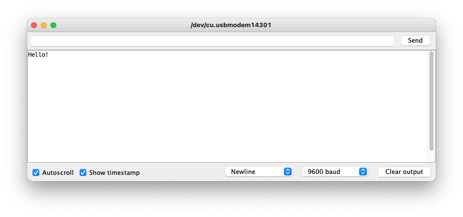
Save and upload the program to the Arduino, then click the top-right button “Serial Monitor” in the Arduino IDE:
The button will open the serial interface monitor on the computer. Make sure it’s tuned to the baud rate set in the program, and you should see the “Hello!” string being printed:
Serial.print() is just one of the functions you can run.
You also have Serial.println() that writes something and adds a \n line terminator, so every message is printed on its own line.
You can also send messages to the Arduino from this serial interface monitor. See the input box with the Send button on top?
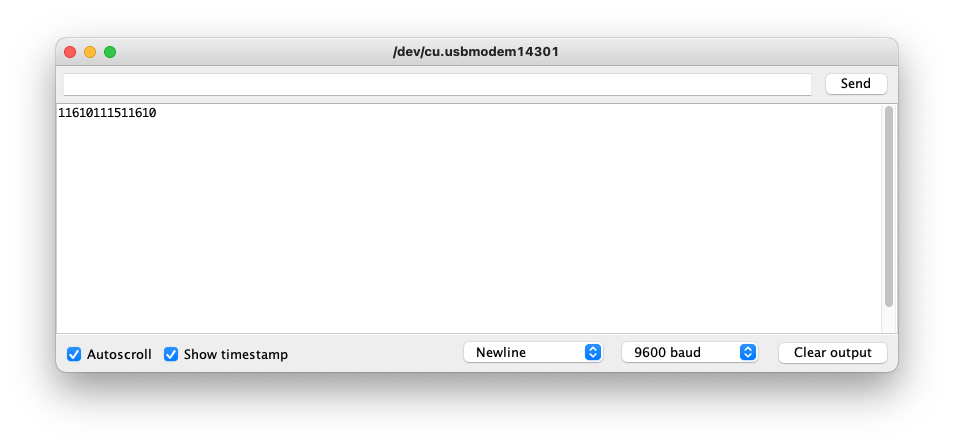
In the Arduino program you can use Serial.read() . Characters are encoded using ASCII, and if you run this program:
You will see in the serial interface printed back the ASCII decimal value of the characters you send. Try writing test and hit Send :
It’s best to use Serial.println() to have each number printed on a single line:
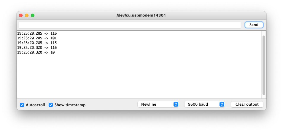
116 is the ASCII encoding for t 101 is the ASCII encoding for e 115 is the ASCII encoding for s
And 10 is the new line character.
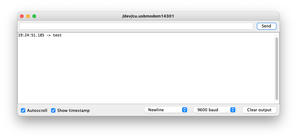
To print the character instead of the ASCII encoding, use the Serial.write() function:
Serial.available() makes sure there’s data ready to be read. It returns -1 if no data is sent, so if we don’t add this check we’ll just see a bunch of -1 repeated in the serial monitor.
There are more functions you can use in the Serial object.
It’s important to note that on the Arduino you have a tx and a rx set of pins. On the Arduino Uno they are pins 0 and 1, on a MKR 1010 they are pins 13 and 14. Do not use those pins for I/O when you use serial communication via USB, or you might have interferences in your data.
That said, those pins are used as the serial interface, which is very useful to communicate directly to other devices, and not with your computer through USB.
Arduino Serial Programming
Some background history and why it is useful for controlling robots and plotters
![]()
The Arduino is great at interfacing directly with various forms of hardware unlike a PC or Mac. Also typically better than a Raspberry Pi. But why is that?
Because when dealing with hardware you want to time things accurately. You don’t want some operating system suddenly taking over control and running another program just while you are busy altering he signal output on some pin. With Arduino only your program is ever running, consuming every clock cycle. You know that next clock cycle, the only instruction executed will be the next one in your program. On a PC, Mac or Raspberry Pi with a multitasking operating system, any program could be executing instructions on the CPU at any given time.
So Arduino is great for interfacing with hardware, but it is also rather weak. You don’t use it for showing big Applications with graphical user interfaces.
This is where serial communications comes in. You can have a program running on your PC or Mac sending data over a serial interface to the Arduino to make it do stuff.
One example would be e.g. getting an Arduino to draw a complicated vector graphics picture with a plotter. That requires a lot of instructions and you don’t want to hardwire them into your Arduino. It is better to have the Arduino listen for drawing instruction from the serial port. Then on the PC you can use a program to select a drawing and send instructions for drawing it over to the Arduino.
Now that we got the rational for serial port communications, let us look at the technical details.
Virtual Serial Ports using USB
One thing that is confusing today is that our computer hardware has evolved from far more primitive types of hardware, but a lot of the old physical parts of that old hardware still exists in modern Macs and PCs. Except the hardware often exists in virtual form.
One example related to TTY and PTY devices on Unix machines. Back in the day before desktop computers we had mainframe computers. Big boxes that several people in a company or university used. We are used to normal computers having one keyboard and one screen connected to them. But these computers essentially had multiple keyboards and screens connected.
More specifically they connected teletype machines, which are essentially type writers. Paper was their screen. They did not have the power to maintain a whole screen for multiple users. Instead a serial RS-232 cable sent keystrokes from the teletyper to the mainframe. On the same cable responses would come back from the mainframe and type characters on the typewriter, which would show on the paper. This is what we call a terminal or console.
On Unix, every connection point to such a terminal was a TTY device (TeleTYpe), represented as a /dev/tty* device in the operating system. Unix was written on such a machine, the PDP-7. You can the teletyper on the right side in the picture below (the device looking like a type writer).
For those puzzled by the ed editor, it is easily understood when you realize that these early mainframe computers could not show a screen continuously which you could move a cursor around and get feedback. The “screen” was just what you saw on paper. Hence you had to look at what was printed and give a command to change, say line two, to something else.
But why are things like /dev/tty* still around when we don't use teletype machines? Because a lot of software was built around this idea. Software running on Unix would be communicating with /dev/tty* assuming there was a teletype machine at the other end.
When we got electronic displays, we started faking these TTY devices instead. On Linux e.g. you can switch between multiple virtual terminals, which to programs running on the operating system just looks like people sitting on different physical teletype machines communicating over RS-232 with the computer.
To make matters even more complex, PTY devices were invented. These are Pseudo TTY devices, with names like /dev/pty* . These are associated mostly with the X-window system. Then you could have multiple programs running, each would could simulate a TTY device. So e.g. a terminal application window would be associated with a PTY which would communicate with a "real" TTY, which is also fake. Same happens when you SSH to another computer. Seen from the applications point of view, it is just communicating with a TTY (faked by a PTY) which translates into a remote communication over the network.
What About USB, RS-232 and TTY?
Okay this was a long winded path to get to talk about USB. I just wanted to get across the idea that it is useful at times for the operating system to trick software running on it into thinking specific hardware is attached to it, which no longer physically exists, such as Teletyper.
Likewise modern computers don’t have RS-232 style connection points anymore. For those too young to remember when they were attached to PCs, they looked like this:
However computers have USB ports. So what the operating system will do, is to create a fake TTY which you can communicate with as if you had an actual serial port. The data is then transmitted over a USB cable. However the software doing the communication has no idea that it is sending data over USB. The Operating system simulates the hardware behavior of a TTY over a RS-232 cable.
One confusing thing is that serial ports are represented by two different devices on Unix, a /dev/tty* and a /dev/cu* device. This is due to a historical distinction between ports connecting directly to a TTY terminal (teletyper) and connections to modems, which may have been used for sending email. The former used TTY and the latter used CU. Apart from the initial setup, they are almost identical, and you can often use them interchangeable.
The key difference is the use of the DTR (Data Terminal Ready) control signal on the RS-232 port. A program talking to DTR would block until DTR signals. A teletyper would send a signal to DTR to indicate it is ready to communicate.
For modems it is a bit different because initially you are giving commands to the modem about who to connect to and how. So in this case DTR is used to signal that a connection has been made. So modems would use the CU device.
The practical consequence of this is that if you are communicating with an Arduino, you can simply cat a /dev/cu* device, and get all the data the Arduino is transmitting. However if you do that with /dev/tty* it will block and you get nothing.
How to Discover Virtual USB Serial Devices
On macOS we can find the serial devices emulated by our USB port like below. However keep in mind, that the serial port to communicate with an Arduino, does not actually get created until you plug the Arduino in. So after you have plugged in the Arduino you can issue these commands:
I have not investigate all these ports, but I’ve found out that I am able to communicate with my Arduino using the /dev/cu.wchusbserial10 and /dev/tty.wchusbserial10 devices. I assume the first device is faking serial communication over wireless bluetooth.
Program to Test Communication with Arduino
Loading up the Arduino IDE, we can type in this program.
In the Tools > Port menu you select the correct serial port. In my case that would be /dev/cu.wchusbserial10 . The Mac then use the USB cable with virtual serial communication to actually transmit the program using /dev/cu.wchusbserial10 . Once the program is transmitted, the Arduino will start running it.
It will then communicate over the same serial communication, due to calling Serial.begin(9600) on setup. In the main loop we keep sending text again and again. You can see this text with e.g.
Just remember to replace /dev/cu.wchusbserial10 with whatever name youre fake USB serial port gets.
Alternatively you can go to Tools > Serial monitor in your Arduino IDE to watch the output.
Yet another alternative is the Unix screen command, which communicates with a TTY through a PTY.
This specifies device to connect to and the baud rate. Make sure the baud rate is the same as the one you used in your Arduino setup() function.
IMPORTANT This command is a bit weird. You cannot exit with the usual Ctrl-C or Ctrl-D . Rather you hit Ctrl+A and then Ctrl+\` . If you don't get this right, you will seemingly exit but cannot connect again, because the PTY is being used.
You need to get back to your previous connection. You do that with lsof which lists all open files, and programs keeping them open. You can then find screen and and a ID to use for disconnecting.
You will then get the chance of existing using Ctrl+A plus Ctrl+\` again.
If nothing works, I’ll just unplug the USB cable.
Echo Example
Here is another example to demonstrate reading and writing to the serial port.
Below is an example interaction in the serial monitor window under the Tools menu. Further details of the serial programming interface can be found here.
Serial.begin()
Sets the data rate in bits per second (baud) for serial data transmission. For communicating with Serial Monitor, make sure to use one of the baud rates listed in the menu at the bottom right corner of its screen. You can, however, specify other rates — for example, to communicate over pins 0 and 1 with a component that requires a particular baud rate.
An optional second argument configures the data, parity, and stop bits. The default is 8 data bits, no parity, one stop bit.
Syntax
Serial.begin(speed)
Serial.begin(speed, config)
Parameters
Serial : serial port object. See the list of available serial ports for each board on the Serial main page.
speed : in bits per second (baud). Allowed data types: long .
config : sets data, parity, and stop bits. Valid values are:
SERIAL_5N1
SERIAL_6N1
SERIAL_7N1
SERIAL_8N1 (the default)
SERIAL_5N2
SERIAL_6N2
SERIAL_7N2
SERIAL_8N2
SERIAL_5E1 : even parity
SERIAL_6E1
SERIAL_7E1
SERIAL_8E1
SERIAL_5E2
SERIAL_6E2
SERIAL_7E2
SERIAL_8E2
SERIAL_5O1 : odd parity
SERIAL_6O1
SERIAL_7O1
SERIAL_8O1
SERIAL_5O2
SERIAL_6O2
SERIAL_7O2
SERIAL_8O2
L1: Intro to Serial
Devices need to communicate. Sensors to microcontrollers. Microcontrollers to computers. Computers to the Internet. And beyond! Many different protocols have been created to support device-to-device communication from Ethernet and Zigbee to WiFi and Bluetooth. In this lesson, we will focus on asynchronous serial communication, specifically TTL serial (Transistor-Transistor Logic Serial)—an enduring standard that has prevailed since the beginning of personal computers and is what the Arduino Serial library uses.
Unlike other popular serial communication protocols like I 2 C and SPI, TTL serial is asynchronous, which means it does not rely on a shared clock signal (precisely timed voltage pulses) paired with its data lines. This has the benefit of fewer wires but does result in a bit of communication overhead for each transmitted “packet” or data frame.
In this lesson, we’ll dive into asynchronous serial communication and how we can use it for bidrectional Computer ↔ Arduino communication.
Serial communication with Arduino
We’ve been using Arduino’s serial functionality since our very first set of lessons (e.g., L3: Serial Debugging). However, we’ve glossed over the details and used serial primarily for debugging rather than Computer ↔ Arduino communication.
On Arduino, we initialize the serial port using Serial.begin() . The Serial.begin() function has two overloaded options:
Once Serial.begin() is called, the Arduino Uno and Leonardo take over Pins 1 and 0 for serial transmission and reception, respectively, and the RX and TX LEDs light up on the board. So, after Serial.begin() is called, you should not use Pins 1 and 0 (unless you’re using them for cross-device communication or to hook up your logic analyzer!).
Thus far, in our lessons, we have been using the first function— begin(unsigned long baud) —which sets the data rate in bits per second (baud). But what about the second function with byte config and what does this parameter mean? We’ll dig in to both below.
Baud rate
The baud rate specifies how fast data is sent over serial, which is expressed in bits-per-second (bps). For communicating with a computer, the Arduino docs recommend: 300 bps, 600, 1200, 2400, 4800, 9600, 14400, 19200, 28800, 38400, 57600, or 115200. Both devices—in this case, the Arduino and the computer—need to be set to the same baud rate to communicate.
Thus far, speed hasn’t been a concern. We’ve typically used 9600 bps (or 9.6 kbps) for transmitting our debugging info. At 9600 bps, the transmitter transmits one new voltage pulse (e.g., HIGH corresponding to +5V and LOW corresponding to 0V) every 1/9600th of a second, which is interpreted as a bit (a 1 or 0) by the receiver. Arduino recommends up to 115200 or 115.2 kbps, which is 12x faster than 9600 (but still slow by today’s networking standards, of course).
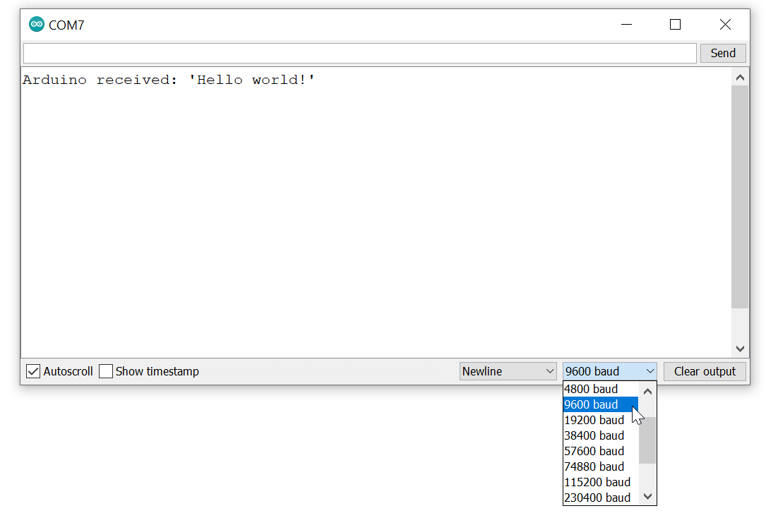
Figure. The Arduino IDE’s Serial Monitor, which has a drop down for baud rate. The baud rate used in Serial.begin(<baud>) must match this drop down menu setting or Serial Monitor will not properly communicate with Arduino.
What’s the fastest serial baud rate?
This will be microcontroller dependent. The Arduino Uno uses a ATmega328P microcontroller, which states a maximum baud rate of 2,000,000 baud (2 Mbps). On Stack Overflow, Connor Wolf found that though the Uno was capable of communicating at 2Mpbs, the Arduino serial library resulted in only an effective 500 kbps communication rate.
The asynchronous serial communication frame
The second function, begin(unsigned long baud, byte config) , allows for an optional argument that configures the serial transmission packet or frame. A serial transmission frame consists of three pieces: data, parity, and synchronization bits (start and stop).
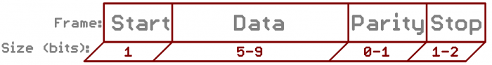
Figure. An asynchronous serial communication frame.
The data bit specifies the length of the data portion of the transmission frame (5-9), the parity bit is a simple form of error detecting code (and can be turned on with ‘1’ or off with ‘0’), and the synchronization bits help demarcate a frame. There is always one start bit at the beginning of a frame but there can be one or two stop bits at the end (though one is most common). On Arduino, the default transmission frame configuration is: 8 data bits, no parity, one stop bit—this is a common configuration.
Importantly, if the baud and config settings do not match between the Arduino and the computer, communication will not work. If something is not working for you, this is the first thing to double check!
Only one computer program can open a serial port at a time
Only one computer program can open a serial port at a time. For example, if you attempt to open Serial Monitor on the same COM port that has been opened by another program, you will receive an error like this: Error opening serial port ‘COM7’. (Port busy) .
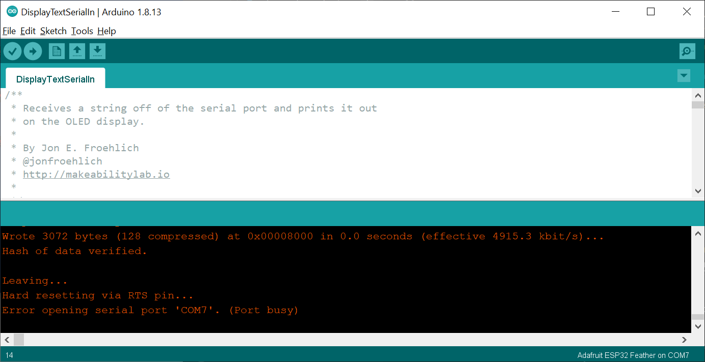 Figure. A demonstration of what happens if you try to open Serial Monitor on a COM port that is already opened by another program. The Arduino IDE shows an error stating Error opening serial port ‘COM7’. (Port busy) .
Similarly, if we attempt to access a previously opened serial port with PowerShell, we receive Access to the port ‘COM7’ is denied.
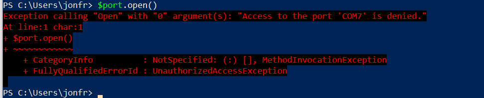 Figure. Only one software program can access a serial port at a time.
Serial buffers
Incoming serial data is stored in a serial buffer, which is read as a first-in, first-out queue (FIFO). On the Arduino, this buffer is 64 bytes (defined in USBAPI.h) and is implemented as a circular or ring buffer. At 9600 baud, this buffer will fill in 53 milliseconds (9600 baud is 1,200 bytes/second or 1 byte every 0.83 millisecond).
Serial to USB? USB to serial?
In the 1980s and 1990s, computers had serial ports like RS-232 connections to support asynchronous serial communication. Now, we use USB (Universal Serial Bus)—a far more sophisticated and efficient serial communication standard that allows multiple devices to communicate over the same wires. However, because asynchronous serial communication persists, USB drivers and our operating systems support asynchronous serial communication over USB. Devices, like the Arduino, include a USB-to-serial converter that shows up as a serial port when you plug them in (just as if you were using an old serial connection). You might see the Arduino device, for example, as a USBtoUART device (UART is Universal Asynchronous Receiver-Transmitter).
Developing serial communication software applications
So, how can we design and implement a computer program to communicate with Arduino via serial? To answer this, let’s decompose serial communication into three high-level layers:
- Hardware layer: How is data communicated over hardware? How many wires are used? What does the voltage signal look like? Thankfully, Arduino handles this for us. And for Computer ↔ Arduino serial communication, serial data is transmitted via the USB cable.
- Serial protocol: What is the format of a serial transmission packet (e.g., the data and parity bits)? How do we compose this packet? Again, we do not really need to worry about this. Arduino uses the standard asynchronous serial protocol and includes the software library Serial to support this. We just need to make sure that both communicating devices are using the same baud rate and data packet configuration.
- Application layer: How do applications communicate together using serial? Aha, this is the key question for this sub-section!
The answer—for better or worse—is completely up to you! If you’re writing serial communication code for both devices (the application on Arduino and the application on your computer), you get to decide how these applications communicate—you’re in complete control. There are, however, some important considerations, including: binary vs. ASCII-encoded data, message formatting, handshaking, and message acknowledgments (call-and-response).
Binary vs. ASCII-encoded data
With serial communication, we can either transmit/receive data as a series of bits (raw binary data) or as alphanumeric characters (ASCII-encoded data).
Reading and writing binary data
To read binary data with Arduino, use readBytes() or readBytesUntil() .
Serial.readBytes() reads bytes from the serial port into a buffer and terminates if the determined length has been read or it times out (see Serial.setTimeout() ). Serial.readBytesUntil() is similar but also has a terminator parameter—if the terminator byte is detected, the function returns all bytes up to the last byte before the terminator. Both functions return the number of bytes read.
To write binary data, we can use Serial.write() , which is an overloaded function:
All three Serial.write() functions return the number of bytes written.
Reading and writing ASCII-encoded data
Reading and writing ASCII-encoded data should feel more familiar. Indeed, for our use-case of serial-based debugging, we’ve been using Serial.print() and Serial.println() , which transmits data as human-readable ASCII text.
Both functions read characters from the serial buffer and store them in a String, which is returned. Serial.readString() terminates if it times out (see Serial.setTimeout() ). Serial.readStringUntil() terminates either if a timeout is reached or if a terminator character is identified.
Both functions return the number of bytes written. See their respective documentation pages for more details: Serial.print() and Serial.println()
Why use binary vs. ASCII?
Why might we want to use binary vs. text encodings? Well, if we are trying to transmit binary data—like an image, video, or song—then communicating via binary is preferred. It’s also more bandwidth efficient (uses fewer bits). However, in our courses, we’re typically transmitting/receiving small amounts of data and it’s beneficial for debugging purposes (and human understanding) to use an ASCII-encoded format.
Binary vs. ASCII example
Let’s take a look at an example. Let’s say we want to transmit a signal that ranges between 0 — 255 from our Arduino to our computer. Because the value only ranges from 0 to 255, we can encode this with 8 bits or a single byte ( 0000 0000 to 1111 1111 or 0x00 and 0xFF in hexadecimal). Sending via binary looks like:
So, for example, if getSignal() returns 15, we would transmit 0000 1111 (or 0x0F ). If getSignal() returns 127, we would transmit 0111 1111 ( 0x7 ). If 255, then 1111 1111 ( 0xFF ). And so on.
However, we could also transmit this using ASCII-encoded data with Serial.println() :
However, now if getSignal() returns 15, we would need to transmit four bytes rather than just one byte. Using the ASCII-encoding chart, we can see that the ASCII encoding for ‘1’ is ASCII 49 or 0011 0001 ( 0x31 ) and ‘5’ is ASCII 53 or 0011 0101 ( 0x35 ). Then, unlike Serial.print() , Serial.println() adds in a carriage return character ‘\r’, which is ASCII 13 or 0000 1101 ( 0x0D ), and then a newline (or linefeed) character ‘\n’, which is ASCII 10 or 0000 1010 ( 0x0A ).
Similarly, if we wanted to transmit 127 or 255 using Serial.println() , we would need five bytes. For example, with 127, we would transmit ‘1’ (ASCII 49 or 0011 0001 ), ‘2’ (ASCII 50 or 0011 0010 ), ‘7’ (ASCII 55 or 0011 0111 ), ‘\r’ (ASCII 13 or 0000 1101 ), ‘\n’ (ASCII 10 or 0000 1010 ).
Both applications need to use same encoding
Note that the receiver needs to know whether data has been transmitted using binary or ASCII encodings. If the latter, the receiver can simply use a method like Serial.readStringUntil(‘\n’) and the data will be automatically transformed into an ASCII-encoded String. If the former, then a method like Serial.readBytes() is necessary and the receiver must know how many bytes are being sent and how to decode them.
For our purposes, we almost always use the ASCII encoding because the benefit of human readability (e.g., sending and receiving text) outweighs efficiency. However, you should consider this on a case-by-case basis depending on your application context, communication medium (wireless vs. wired), and power requirements (e.g., low power applications should minimize transceiving).
Formatting messages
The above example simply sent one value per transmission. For binary, we sent one byte per new signal read; for ASCII-encoding, we sent one line per new signal read. However, it’s likely that you’ll want to transmit and receive multiple values. How do we do this?
Again, it’s completely up to you! If you’re using ASCII-encoded transceiving, you could use a comma-separated value (CSV) format, JSON, or some other messaging format of your own design.
As you’ll commonly see in our demo code, we use a simple CSV format like this:
For example, if sensorVal1 is 896, sensorVal1 943, and sensorVal3 is 349, then the above code would send a text string that looks like 896, 943, 349\r\n .
On the receiving end, we might use regex for parsing or write our own parsing code like this:
This example assumes that data is in the order of sensorVal1, sensorVal2, sensorVal3 and that each received line is the same. To make this communication scheme more flexible, you could transmit a modified CSV with variable names (like key,value pairs) or use JSON. Towards the former, you could transmit the key,value pairs as: “ sensorVal1=896, sensorVal2=943, sensorVal3=349 ”. The receiver would then parse both the variable names and their values.
In all of our examples, we use very simple CSV formatting with ASCII-encoded transceiving. But feel free to do things differently!
Handshaking
When two devices begin communicating—whether via serial or some other protocol—it’s common to handshake. That is, to transmit and receive a small set of initial messages to establish parameters for communication and to synchronize statuses. For example, upon connection establishment, you might have your two devices exchange their current set of stored values.
Acknowledging data
Similarly, if you want to ensure that data has arrived and been parsed correctly. You might decide to transmit back an ‘OK’ message after each line of receive data along with a hash (this hash can be used by the original transmitter to verify data arrival).
Example serial programs
Below, we are going to show a few different examples using the command line, Python, and then JavaScript. To keep things simple, in this lesson, we are going to focus on unidirectional communication from the computer to the Arduino ( Computer → Arduino ). That is, the computer will send data and the Arduino will receive data. Later, we will cover Arduino → Computer and bidirectional (duplex) communication Computer ↔ Arduino .
And actually, in all of our serial lessons—including this one—we will have the Arduino transmit something back to the computer to aid with debugging and ensure the Arduino received what we expected. We call this an echo message. You’ll see!
Simple Arduino serial receiver program
For our examples below, we will be running a simple program on our Arduino that reads ASCII-encoded data off of the serial port, parses that data into an integer, and uses analogWrite to output that integer to an output pin. In this case, we have hooked up a red LED with a current limiting resistor to the OUTPUT_PIN , which is set to LED_BUILTIN (Pin 13 on the Arduino Uno and Leonardo). The entire program looks like this:
Code. This code is available as SimpleSerialIn.ino on GitHub. We will actually be using SimpleSerialInOLED.ino in our videos.
Demo circuit
And here’s the corresponding circuit for the program above, which consists of a current-limiting resistor and LED attached to Pin 13. Of course, you could build almost any circuit to respond to serial input. But let’s keep things simple!
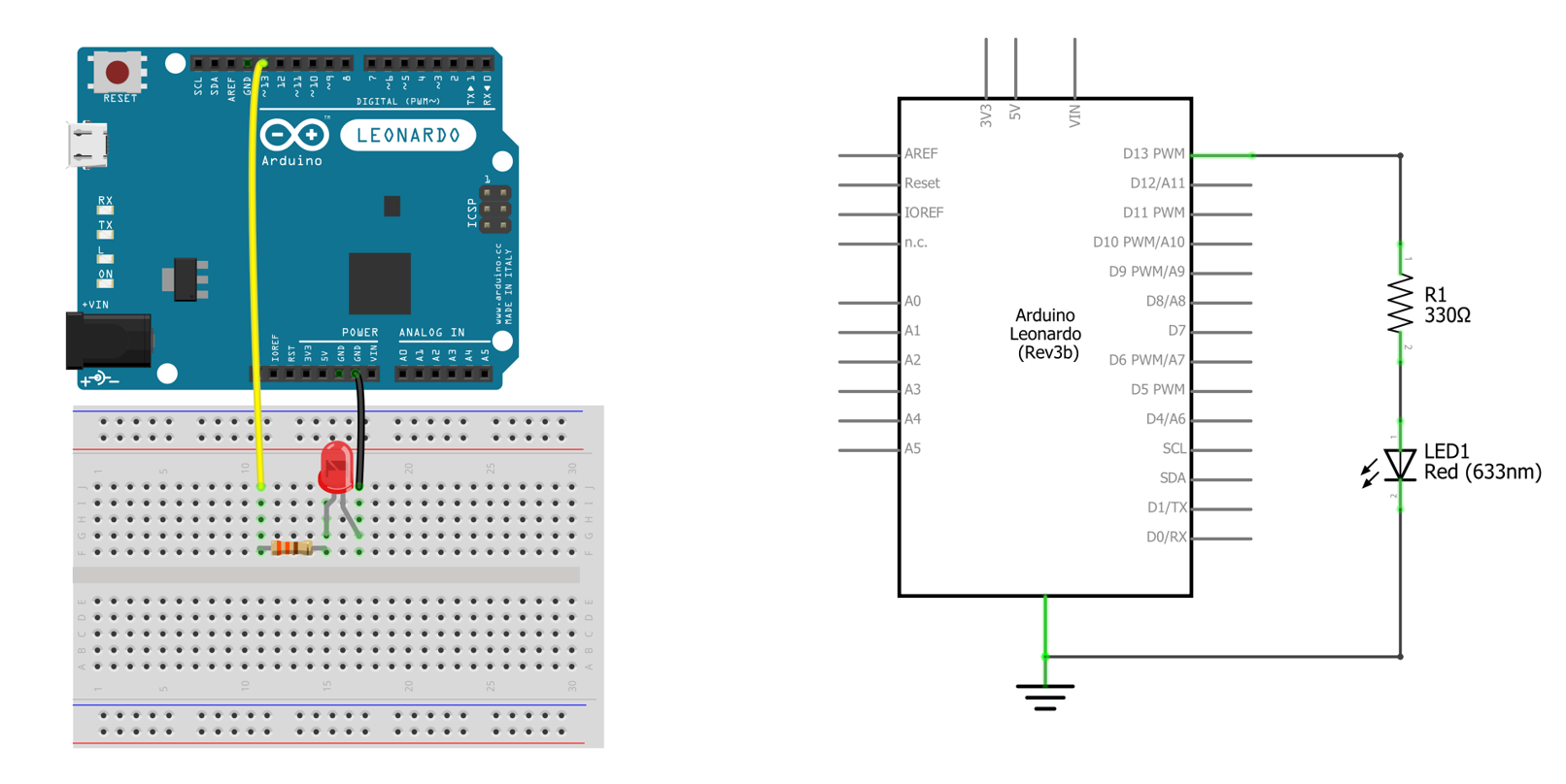 Figure. The corresponding circuit for SimpleSerialIn.ino. Made in Fritzing and PowerPoint.
Using Serial Monitor
Let’s begin by using our now familiar Arduino IDE Serial Monitor tool. With SimpleSerialIn.ino loaded on your Arduino and your Arduino connected to your computer, open the Serial Monitor and send data to our Arduino. Make sure you’ve selected the same baud rate used in Serial.begin(<baud rate>) .
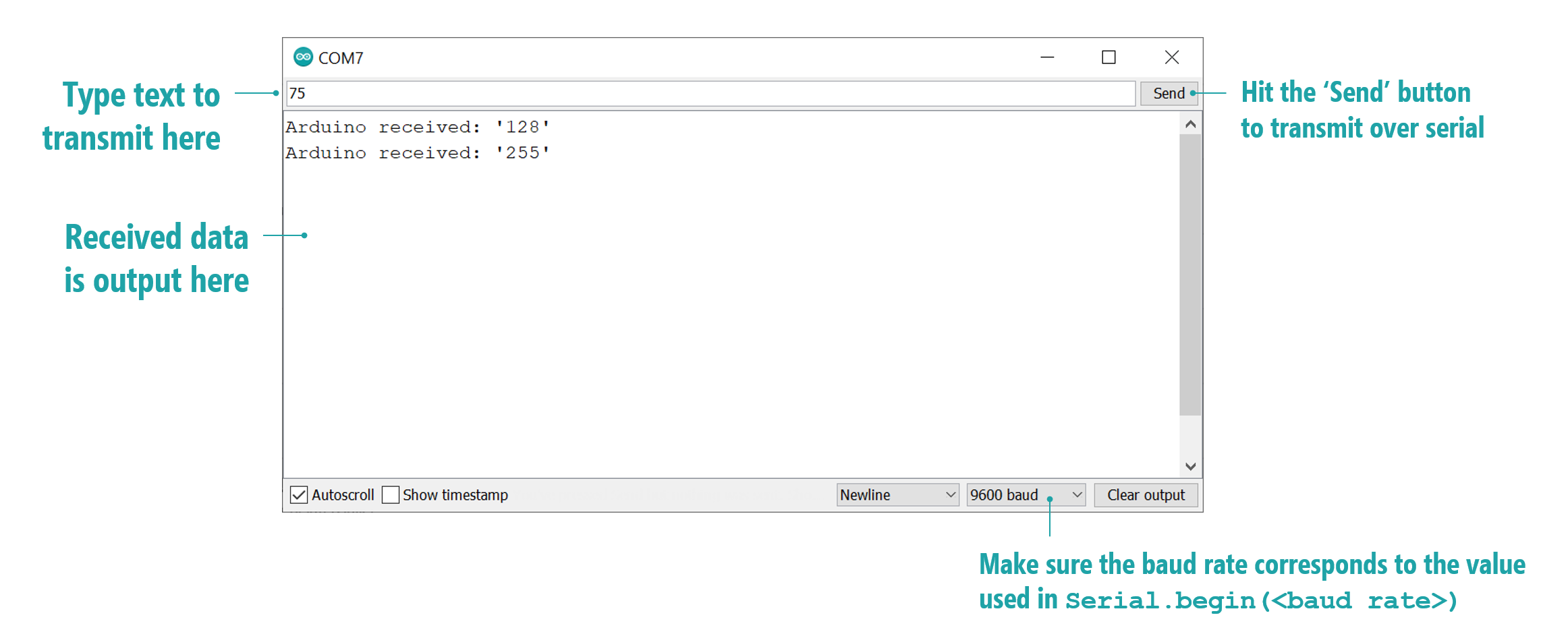 Figure An annotated screenshot the Arduino IDE’s Serial Monitor tool for sending and receiving serial data. The data “echoed” back to our Arduino is shown in the autoscrolling textfield (where it says “Arduino received…”).
Video demo using Serial Monitor
Here’s a video demonstration of sending ASCII-encoded text via Serial Monitor to the Arduino running SimpleSerialInOLED.ino.
Video. A video demonstrating using the Arduino IDE Serial Monitor tool to communicate with the Arduino running SimpleSerialIn.ino. For this video, we are using a slightly modified program called SimpleSerialInOLED.ino along with an OLED display. This allows you to more easily see the received values.
Notice how we are able to print out what the Arduino receives because the Arduino cpde echos the received data back over serial using Serial.print . This is optional but helpful!
Command lines tools
While we’ve thus far emphasized the Arduino IDE’s Serial Monitor, there is nothing special or unique about that tool. We can use any application or programming language with serial support. Below, we’ll show how to use command line tools for both Windows and Mac/Linux before showing an example with Python (but C#, Objective C, Java, etc. would work too!)
Windows
On Windows, we can use the PowerShell terminal, which is built into Windows 10, to read and write data from the serial port. For this, we’ll follow the official PowerShell blog.
First, to find the available serial ports, we can use getportnames() .
Then, we’ll create a SerialPort object, which takes the COM port, the baud rate, serial configuration parameters (parity bit, data bit length, and stop bit).
Now open this port.
Write to the port using ASCII-encoded text with WriteLine(<str>) :
Similarly, to read from the port, use ReadLine() :
Finally, to close the port, use Close() .
Thus, the full program is simply:
Video demo using Windows PowerShell
Here’s a video demonstration:
Video. A video demonstrating using Windows PowerShell to communicate with the Arduino running SimpleSerialIn.ino. For this video, we are using a slightly modified program called SimpleSerialInOLED.ino along with an OLED display. This allows you to more easily see the received values.
Mac and Linux
On Mac and Linux, we can use the screen command as described by this Sparkfun tutorial. Screen should be installed by default on Mac. If it’s not installed on Linux, install it with sudo apt-get install screen .
First, we need to enumerate the available ports. Type:
In this case, the Arduino is listed as /dev/tty.SLAB_USBtoUART . We can connect to it via screen by typing screen <port_name> <baud_rate> :
You terminal should go blank with a flashing cursor. You are now connected to that port. Anything you write will be instantly sent to Arduino as ASCII-encoded text.
To disconnect, you must type control-a followed by control-\ . The screen program will then ask if you want to exit. Type y .
Python
Finally, let’s make a simple program in Python to write and read data off the serial port. This is simply to demonstrate the overall programming concepts before we dive more deeply into JavaScript solutions for our other lessons. Again, you can really use any programming language you like!
For serial communication with Python, we’ll use the pySerial library. With Python3 installed, open your terminal and type:
This will install the pySerial library. pySerial is quite straightforward and pySerial’s “fast intro” docs provide a number of examples.
Let’s write a quick Python program to communicate with SimpleSerialIn.ino.
First, import the required libraries and then create and initialize a pySerial Serial object.
Now, write code to ask the user to input a number between 0 and 255:
Then encode this data as a string. You can force it to ASCII via num.encode(«ascii», «ignore»)
Now we’re ready to send the data using pySerial’s write(<data>) function.
Finally, read the response from the Arduino and print it out:
And that’s it! This code is available as serial_demo.py in our GitHub. Note, after creating the Serial object, we wrap everything in a While True: statement to infinitely loop and ask for new user data. See video below.
Video demo using Python
Video. A video demonstrating using Python3 with pySerial to communicate with the Arduino running SimpleSerialIn.ino. For this video, we are using a slightly modified program called SimpleSerialInOLED.ino along with an OLED display. This allows you to more easily see the received values.
Using Python for real-time gesture recognition
Of course, we can do significantly more interesting things using serial communication. In the video below, for example, we demonstrate a Python program that reads in real-time accelerometer data sent via the Arduino over serial and classifies gestures (using a template matching).
Video. A video demonstrating real-time gesture recognition using 3-axis accelerometer data sent via the Arduino over serial. We wrote the gesture recognizer in Python; however, we are not linking to the code because we use it as an assignment in some of our courses. You can learn more in our Signal Classification lesson series.
There is a world of possibilities here. And we’ll begin to explore them in this lesson series!
Activity
For your prototyping journals, run SimpleSerialIn.ino or SimpleSerialInOLED.ino with the appropriate circuit and choose one of the above approaches (or develop your own!) to communicate with the Arduino. Take a video and reflect on what you’ve learned in this lesson.
Resources
Videos
Serial 1: Introduction, NYU ITP Physical Computing course video
Serial 2: Logic Analyzer and ASCII, NYU ITP Physical Computing course video
Next Lesson
In the next lesson, we’ll apply our newfound serial knowledge to communicating with our Arduino via our web browsers using the Web Serial API.