Arkadian.eu
Vex motors (with the Vex Motor Controller 29) are essentially servos. To use them on an Arduino as motors, all you need to do is figure out the “angles” that give you the right speed.
The problem is that all motors are slightly different. To find the right angles for my motors, I simply modified the “knob” example on the Arduino Aplication (1.0.1) to this:
#include <Servo.h> // create servo object to control a servo Servo myservo; // analog pin used to connect the potentiometer int potpin = 0; // variable to read the value from the analog pin int val; // vex motor value int vex; void setup() < myservo.attach(11); Serial.begin(9600); >void loop()
By adjusting the potentiometer a number of “VEX” angle values are generated, from 0 to 180. Make sure that you have the serial monitor up!
My motor was working at the following angles:
20 degrees: move forward
138 degrees: move backward
91 degrees: stop motor
based on the above findings, we can then test the VEX motor by using the following arduino sketch:
First Foray into Robotics
You should not use the arduino analogWrite PWM function to drive a hobby servo. They do not use PWM and could damage a servo or speed controller. Its confusing because many references do incorrectly use the term PWM in articles about servos. But hobby servos and speed controllers expect different pulse timings from that provided by analogWrite.
When controlling a servo, typically the on time of the pulse will be varied from around 1 millisecond to 2 milliseconds with the off time around 20 milliseconds.
+—+ +—+
| | | |
| | | |
| | | |
—+ +—————-+ +——
—>
+——+ +——+
| | | |
| | | |
| | | |
—+ +————+ +——
—>
This is called Pulse Position Modulation and is not the same as PWM as used in the Arduino analogWrite. PWM (Pulse Width Modulation) varies the ratio of on time to off time to vary the overall signal level and are not suitable for driving a hobby servo.
There are many Arduino libraries that are suitable for driving servos and speed controllers – here are a few of the references:
The servo library included in the Arduino download – can control one or two servos on pins 9 and 10: http://www.arduino.cc/en/Reference/Servo
Now there are a couple of differences in performance between the Arduino servo control system and the VEX one. In VEX, you send a range of values between 0 and 255 (or -127 to 127 in RobotC), with 127 as center (0 for RobotC). However in the Arduino library, there are two possible ways to control a servo interface/motor. The first, and probably most user-friendly is based off of actual servos (not the continuous-rotation servos like the VEX motors). You send the servo/motor a value between 0 and 180, based off of degrees, with 90 as center. This reduces resolution a bit, but generally works just fine, since adding one or two points on the 0-255 scale doesn’t make a noticeable difference anyway. When using a servo, this comes with a nice little surprise. Whereas with VEX and most other servo controllers, you get 120 degrees of travel, with the Arduino controlling it, you actually get a full 180 degrees! I think it adds a bit in both directions, but I’m not sure. I have no idea if this amounts to an increase in speed of VEX motors, but I would assume not.
The second way to control a servo in Arduino is to feed the servo function the raw pulse duration in microseconds. For your average servo, it’s looking for a value between 1 and 2 milliseconds, or 1000 and 2000 uS (microseconds). However, with the increased range of travel for the Arduino servo driver, valid values are actually from 544 to 2400 uS. Again, I don’t know how the extended range impacts the VEX motors.
If you want to control VEX motors with minimal modification of code written for the VEX, I would use the byte values (0-255) from the code and the map() function in Arduino to transform the byte range directly to the microsecond range from 1000 to 2000 uS, since the 0-180 range is mapped to microseconds anyway. The fastest way to write microsecond values to servo outputs is to use the Servo.writeMicroseconds() function, although Servo.write() will also work, it just takes a couple more steps to check to see if the value is in the degrees range or the microseconds range.
As for circuitry, I’ve used one 7.2v power supply, and it worked fine. Plug the 7.2v into a breadboard or PCB or perfboard, run ground to the ground on the Arduino, and the +7.2v power line to Vin on the Arduino (NOT +3.3v or +5v, those come off of regulators on the Arduino board). Then just run ground to the black line of the VEX motor, power to the orange line, and a signal line from a digital output on the Arduino to the white wire on the motor. But yes, if you do want to use two separate power supplies for whatever reason, connect the grounds. As long as you don’t have any power lines going between the two systems, there won’t be a problem.
VEX + Arduino Control — Best of both worlds!
Many schools and homes have VEX robotics systems. It’s an awesome and amazing platform. I’ve casually mentioned to several friends that integrating VEX with Arduino is super simple to do. Here’s a quick snap-shot at what we got working today.
- Arduino
- Robotics
- Wireless
There are thousands of schools using VEX in the classroom. VEX started with a simple PIC microcontroller system and recently upgraded their platform to a Cortex based system. These are fantastic, high-powered, fast systems that work well in many classrooms. There are a variety of programming environments for VEX from easyC, robotC, to ModKit and Flowol. However, there is also a fast growing population of schools using Arduino to teach basic microcontroller programming and electronics. How can we combine these two realms?
VEX has a fantastic building platform. If you are looking at expanding your robotics, mechatronics, or general structures program — I encourage you to look into VEX. Their structural and mechanics system is fully modular and works with a minimum number of unique parts and pieces. One of the struggles I have heard from teachers is how can we integrate Arduino with what we do with VEX. Here’s a quick summary of what we got working. A more in depth tutorial is in the works.
Human Control
Using Arduino as an autonomous controller for VEX motors is a pretty easy problem to solve. The bigger problem to tackle is replicating the «tele-operated» human-control that VEX provides.
VEX offers a slick WiFi Joystick control and default firmware on their Cortex controller that allows a quick «plug-and-play» experience. I wanted to re-create the same experience with as few custom parts as possible.

A quick search for USB joystcks on-line came up quite a few different options. I tried this low-cost controller, but settled with the Logitech F310 instead. It’s currently availble on Amazon for $18.99 and features nearly all of the same buttons and controls as the traditional VEXnet joystick.

Hardware Used
Aside from the joystick and the Clawbot kit from VEX, here is a wishlist of all the parts I used on this build. With the battery, the total retail cost is about $200. What I really like about this solution is that it opens up the controller to all sorts of other interfaces, sensors, and peripherals that you can build and hack on.
If you want to try this, you will need to pair your XBee Radios. You can check out this tutorial if you’ve never done this before:
Control Programming
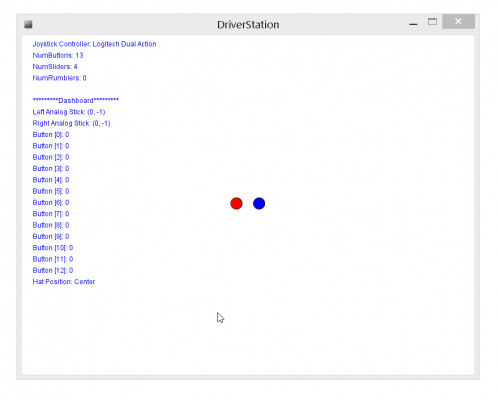
Now I had a comparable controller, I needed an interface to the Arduino. Naturally, I looked into Processing. The GameControlPlus library in Processing handles a lot of the back-end I/O for the joystick. Here is a rough DriverStation program example in Processing. You will need to install both the VSync and the GameControlPlus libraries to use this example. You can add both of these directly in Processing from the Sketch —> Add Library menu.
The code is pretty well commented. In general, what it does is interface a joystick controller and read in all of the inputs from the joystick and it sends this to the Arduino through the serial COM port associated with the XBee Radio. Alternatively, you can use a USB cable tether directly to the Arduino and for-go the wireless Xbee part — just make sure that you specify the correct COM port.
Right click here and select file save-as to download this code.
Arduino Code
I learned a few things as I wrote this example. Interfacing the H-Bridge controller on the ArduMoto Shield was easy. The ArduMoto Shield is perfect for driving and controlling the VEX motors. However, the ArduMoto Shield only has two channels. Additional motors require an external motor controller. Thankfully, VEX includes these in their Clawbot kit. The VEX Motor Controller 29 has a small PIC microcontroller embedded inside it. It responds to a 50 Hz pulse-width modulation (PWM) signal with a pulse width that varies from 1000 uS to 2000 uS. 1000 uS corresponds to full speed reverse and 2000 uS corresponds to full speed forward. 1500 uS, logically, causes the motor to stop.
Using the Servo library, I wrote a small function vexMotorWrite(Servo motorObj, int speed) that scales a speed value (-255 to +255) to a Servo pulse from 1000 uS to 2000 uS. You must pass this function the Servo motorObject tied to the VEX Motor Controller.
What’s next?
Look for an in-depth tutorial around this. A lot of tips around using Xbees, the Servo library, and integrating all of these things together. In the meantime, let us know if you end up trying this in your own class! Happy hacking!
Vex Library
The VEX library is used in the EG1004 course to control the VEX robot and sensors using Arduino. The library is designed to more easily access the robot’s functionality. For more information on coding with Arduino, please reference the Arduino Coding Guide
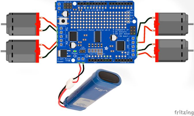
The library is intended for use with the Adafruit Motor Shield V2, and VEX EDR 2-wire motors.
The library allows you to interface with the following sensors:
- MPU6050 Accelerometer and Gyroscope Sensor
- HC SR04 and VEX Ultrasonic Sensor
- VEX Touch/Button and VEX Limit Switch Sensor
- IR Obstacle Avoidance Sensor
The library also allows for the following functions of the motor board:
- Control single motor speed and direction
- Control two motors speed and direction simultaneously
Download the library files here
Library Structure
This library relies on multiple 3rd party libraries, including MPU6050, I2Cdev, and Adafruit Motor Shield V2, as well as inbuilt Arduino libraries including Wire.
There is one main class that controls the robot:
- Vex: commands the motor shield, and controls the motors for all robot movement
There are 2 classes that control different sensors:
- Gyro: reads data from the MPU6050 and provides the Euler angles around 3 axises
- Ultrasonic: reads the distance from itself to the nearest object it senses
Examples
Example files can be found by clicking on File>Examples>Vex. These Arduino C codes provided show the possibilities of the robot and provide tests for different functions.
- Movement Test: tests the standard robot movements, such as forward, turns, and claw movement
- Gyro Library Test: tests the gyro sensor to display the x,y, and z Euler angles
- Gyro Turning Test: tells the robot to do a 90o left and right turn based on the gyro sensor
- IR Obstacle Test: tests the IR obstacle avoidance sensor
- Touch Test: tests the touch sensor/limit switch to display whether or not the button/switch is pressed
- Ultrasonic Test: test the ultrasonic sensor by telling the robot to move forward until it is 5cm away from an obstacle
Importing the Library
- Open your main Arduino File.
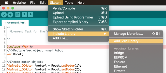
- At the top of your screen, click on ‘Sketch,’ then ‘Include Library,’ then ‘Add .ZIP Library’’
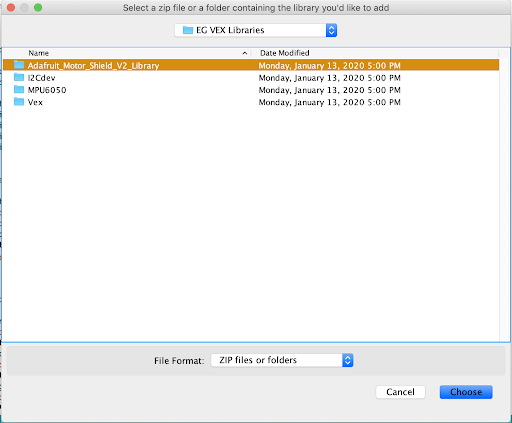
- Next, find the library you would like to include. Make sure the file is unzipped. (If using Windows, to unzip a file, right-click the file and select ‘Extract All’). You must upload all four files in ‘EG VEX Libraries.’ Note: Arduino does not let you upload all of the libraries at once so repeat steps 2 and 3.
- Make sure to have ‘#include <Vex.h> ‘ at the top of your file.

Alternative Way to Import the Library
- Download the zipped EG VEX Libraries file here
- Extract the four libraries to separate folders
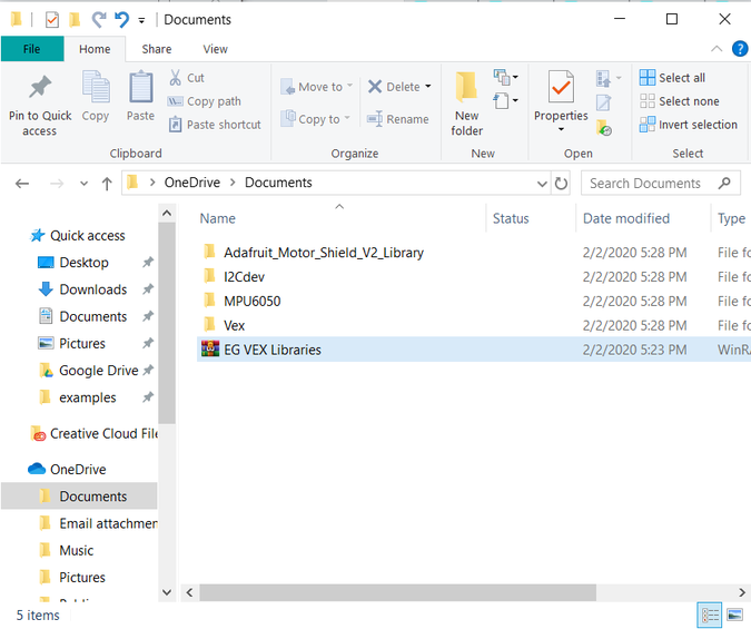
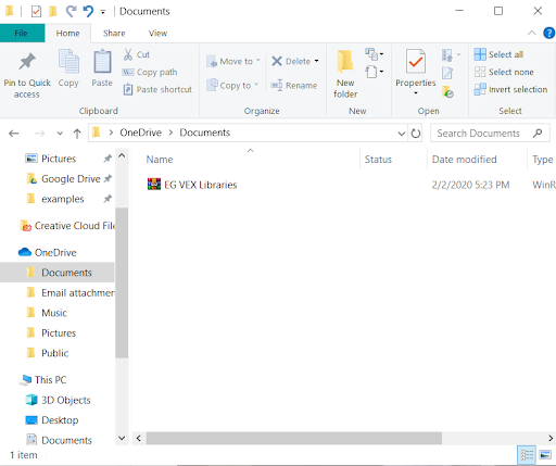
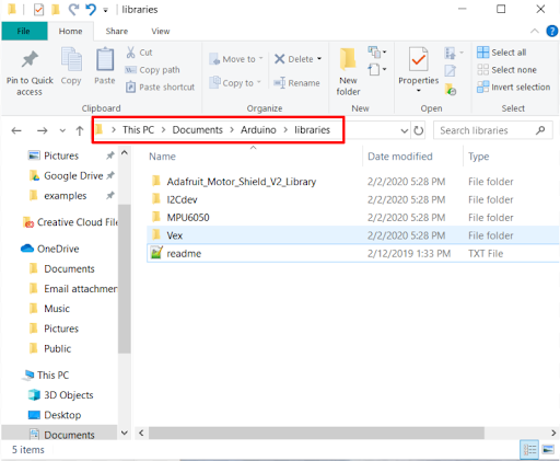
- Move the four libraries to the Arduino libraries folder
- This is usually Documents/Arduino/Libraries
- Restart the Arduino IDE to load the libraries
Vex Class
This class is used to interface with the motors connected to the Adafruit Motor Shield. The shield can support up to 4 DC motors and uses its own power source separate from the Arduino RedBoard.
Wiring
The Adafruit Motor Shield comes with pins that connect the shield directly on top of the microcontroller. The shield can then be used just like the microcontroller, as it also has the standard pins used for the Arduino. In order to use the motor terminals labeled M1, M2, M3, and M4, the shield must be powered. For the VEX library, this should be done by connecting an external power source to the terminal shown in Figure 1. Figure 1 shows how to wire the motor shield with four DC motors and an external battery.
Methods
Constructor
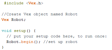
- In order to create a Vex object, the constructor must be called. Creating a Vex object allows you to call on the methods, which can also be referred to as functions, within the Vex Class. The constructor for a Vex object is empty meaning it has no parameters.
- Vex vex;
- None
- None
- Create a Vex object named robot:

Note: All constructors should be called outside of functions setup() and loop(). Additionally, your Vex object can have any name (i.e Robot, vex, etc).
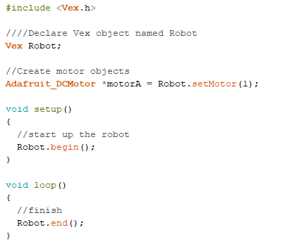
begin()
- The begin() method initializes the VEX robot. It must be called in the setup() function to use any other Vex methods.
Note: begin() does not initialize sensors. Refer to the documentation for the wanted sensor for reference on initializing these other modules.
- vex.begin();
- None
- None
setMotor()
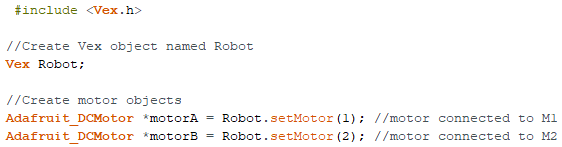
- The setMotor() method sets up the motors for use with the motor shield. This function must be called in order to create the motor objects needed for the moveMotor() and moveTank() methods. It also cannot be used alone and must be called when setting an Adafruit_DCMotor object. See the example below for correct usage of the setMotor() method
- Adafruit_DCMotor* motor = vex.setMotor(port);
- port: An integer between 1 and 4, representing the motor port being used on the motor shield
- An Adafruit_DCMotor* object
- The end() method stops all robot movement. It is meant for use at the end of the code, to stop the robot from looping the original code over and over again.
Note: this method places the code within an infinite loop, therefore any code written after this method is called will not be run.
- vex.end();
- None
- None
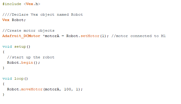
moveMotor()
- The moveMotor() method allows for the movement of a single motor, for a set power and time
- vex.moveMotor(motor, power, time);
- motor: an Adafruit_DCMotor* object, previously created using the setMotor() method.
- power: a double between -100 and 100. Positive numbers will move the motor clockwise, while negative numbers will move the motor counterclockwise. 0 will cause the motor to not move.
- time: a positive double, representing the number of seconds to run the motor.
- None
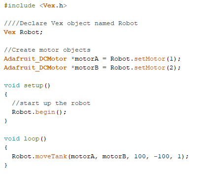
moveTank()
- The moveTank() method allows for the movement of two motors simultaneously, for two different power values, over a set period of time
- vex.moveTank(motor1, motor2, power1, power2, time);
- motor1: an Adafruit_DCMotor* object, previously created using the setMotor() method
- motor2: an Adafruit_DCMotor* object, previously created using the setMotor() method
- power1: a double between -100 and 100. This value controls the power of motor1. Positive numbers will move the motor clockwise, while negative numbers will move the motor counterclockwise. 0 will cause the motor to not move.
- power2: a double between -100 and 100. This value controls the power of motor2. Positive numbers will move the motor clockwise, while negative numbers will move the motor counterclockwise. 0 will cause the motor to not move.
- time: a positive double, representing the number of seconds to run the motor
Gyro Class
This class is used to interface with the MPU6050 Accelerometer and Gyroscope. It is created specifically to provide the values of the Euler Angles as calculated from the gyroscope. Note: As the Gyro class is made specifically for this function, it cannot be used to access the additional functionalities of the MPU6050 device. Any other use of the MPU6050 outside of this class is at the discretion of the student.
Wiring
Figure 2 shows how to wire the MPU6050 sensor. Note that the Int pin on the MPU6050 must be connected to digital pin 2 on the Arduino board for the sensor to work within this library